Posted on 18/08/2017 at 07:22
Elvira : Rebuilding the 36hp, episode 9 : Flywheel and Cluch


episode 9 : Flywheel & Clutch

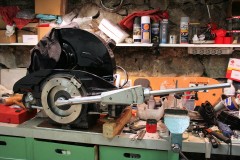
I finally came to the conclusion that I possibly had thrown it away by mistake (!), and right before I started looking for another one (they're not easy to come by, them 36hp flywheels), I gave a call to my friend Laurent, to ask if I had not left my flywheel at his workshop when we closed the engine block... I didn't expect much as I thought I remembered him telling me it would be better to keep all the parts together...
But he told me "yes, sure your flywheel is here!!".
GRRAAaaaaRRRGHh!!!! So much time lost! Damn, I could kick myself in the ass! #StupidOfTheYear
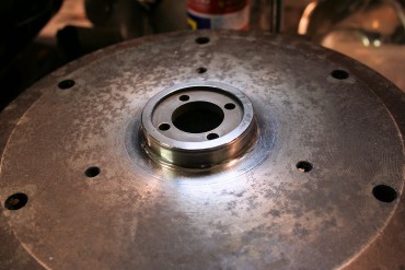
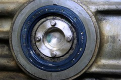
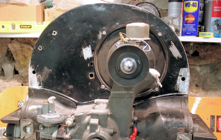
Anywayyyyy... On my flywheel, the oil seal running surface was pretty dull : some pitting, lots of oxydation... In order to avoir any oil leakage from there, I had to do something about it.
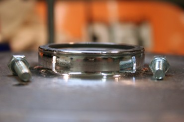
So I polished the running surface, starting with dry sandpaper 320 / 400 / 600 grit, then with oil (WD40 is your friend) 800 / 1000 / 1200 / 1500 / 2000 grit. I ultimately use 3 polishing compounds, of increasingly finer grit, applied with a felt wheel on my Dremel tool.
I take this opportunity to ever so slightly round the top angle, to make sure the oil seal won't get damaged when putting everything together.
And Tadaaaa! Shiny-shiny!
That's the opportunity for me to bring out my BIG torque wrench, the one I use to reach the 35 mKg needed to properly tighten flywheels and rear wheels' central nut.
First step, find a set of shims, cuz' as expected, the ones I have don't allow me to adjust the play correctly... And as usual, the 36hp shims aren't the same as Type 1's, and much harder to source!
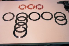
Long story short, I buy a couple of 0.32mm shims from VW Classic Parts, take out the ones in my original engine, and I end up with a pretty good assortment of shims in various thicknesses, plus 3 paper gaskets of various thicknesses.
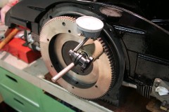
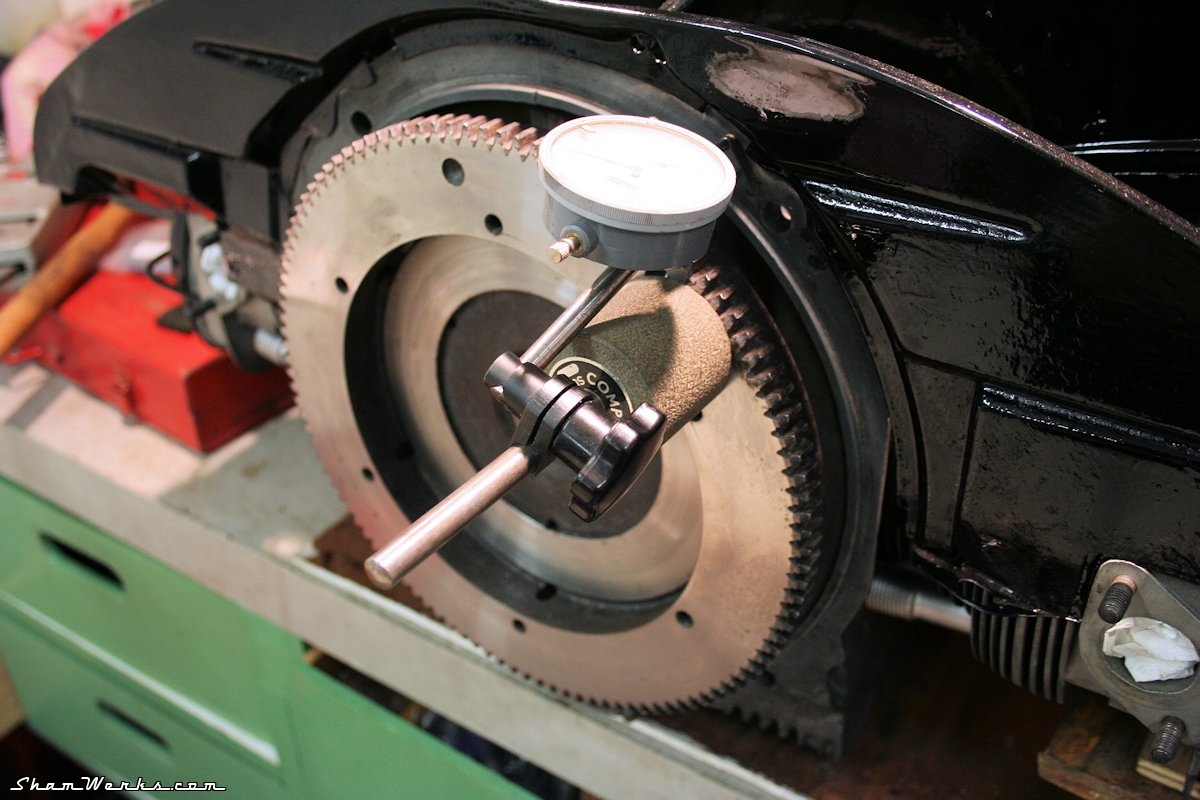
Without the paper gasket between the flywheel and the crankshaft, I get a little over 0.03mm of end play, measured with a dial indicator. After 4 assembly/torquing/disassembly sessions, I manage to find the right set of 3 shims (always install 3 of them, for relative rotation speed reasons) to get 0.10mm of end play with the paper gasket on. I would have prefered it to be a tiny bit tighter, like 0.08mm, but it will do. I give the oil seal a good dose of lubricant, put the flywheel on, and torque the central nut (with a drop of blue Loctite medium threadlocker). Just for later reference, if you ever had to look for 36hp shims : here are the VW references. Good hunting! :
- 111 105 281 : 0.24 mm
- 111 105 283 : 0.30 mm
- 111 105 285 : 0.32 mm
- 111 105 287 : 0.34 mm
- 111 105 289 : 0.36 mm
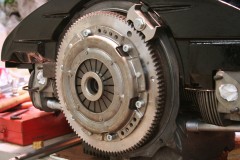
The flywheel had been re-surfaced and balanced with the crank and clutch assy (work done by Slide Perf in March 2012!! It's really high time for me to finish this engine!
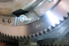
A "1" mark had been stamped to make sure the flywheel is in the same position as it was balanced ; same for the clutch assembly, with a "0" mark. At least, the bloody thing shouldn't wobble around.
The clutch assy screws are torqued (2.5 mKg) and secured with the usual drop of Loctite.
That's it for today! Yet another checkbox ticked out!
Hopefully this engine should run in no time now! (wishfull thinking...)
Posted on 07/03/2017 at 21:18
Elvira : Rebuilding the 36hp, episode 8 : cooler, tinware and shroud


episode 8 : cooler, tinware and shroud
Oil Cooler
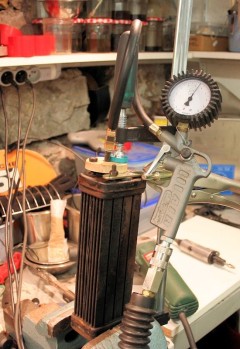
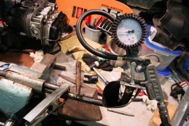
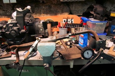
I start by sprucing up my oil cooler. I put it under pressure to ensure it is still air tight, using a bicycle tire valve (same method I recently used for my intake manifold). It holds at 5.5 bars : we're good here.Thorough cleaning using brake cleaning fluid and compressed air, giving the whole damn thing a good shake to make sure I get rid of any muck sitting in all the nooks and crannies inside...
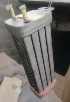
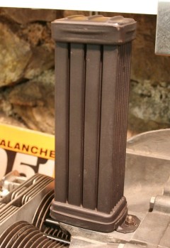
Then I give it a light sandblast to remove the flaking off original paint (I obviously first taped shut the oil in/out holes), and then a thin coat of high temperature spray paint, just to prevent rust. Just to make sure the sandblasting did not affect the oil cooler, I give it another pressure test ; still holds at 6bars, we're still good (#paranoid).
It then goes back on the engine with a couple of brand new gaskets. Next !
Fan shroud and tinware
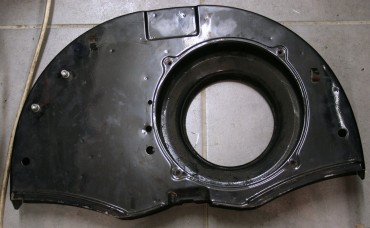
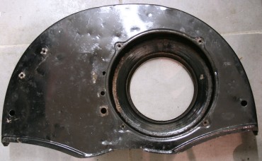
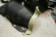
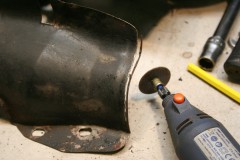
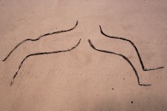
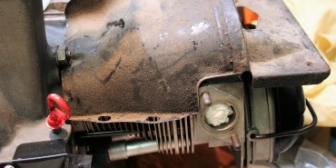
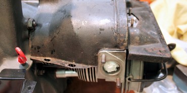
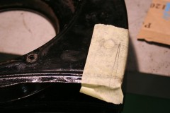
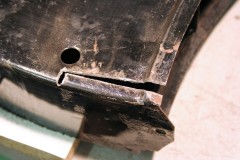
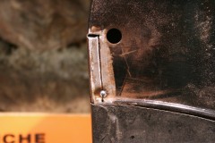
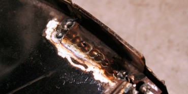
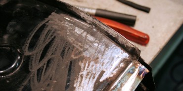
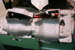
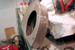
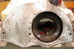
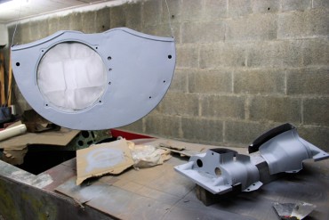
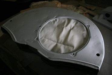
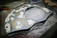
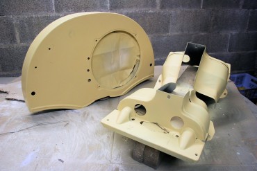
Again, because of my modified cylinder heads, I gotta touch up the tinware to make it fit the new engine width.Since I'd rather keep my original tinware untouched, I managed to get my hands on a new set of tinware and fan shroud to modify them. That new shroud is slightly different than my original one, it doesn't feature the top recess (which makes room for the oil bath air cleaner)... Prolly an older shroud ; well, since I wanna move later to a two carbs setup... For the two over-cylinder tins , it's pretty straight forward : I just Dremel-cut 3.2mm at their base. Done. For the shroud, well, it's a bit more tricky. I make two triangular relief cuts on each side, which I then bend inward and weld back shut... And there you go, a 6.4mm narrower shroud.
Well, it did take a few hours to weld/grind!
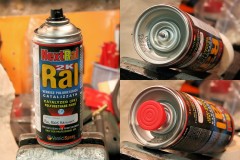
I wanted to give a shot to this product for a while now, as a friend recommended it to me... Not exactly cheap (25€ the spray can at Vernicispray), but I gotta say, the result has NOTHING to do with that of a standard spray can! Shiny! Well, sure, as I used it in my dusty garage, it's not perfect by any means, but way good enough for engine tinware as far as I'm concerned.
In order to use these spray cans, you first have to hit the bottom cartridge, that holds the hardening component, then shake the damn thing a couple of minutes. You than have 6 to 7 hours to use the product before it hardens... So you need a bit of organization if you want to spray more to one coat!
Just one drawback I experienced : it might be because the temperature in my garage was too low, but by the end of the can, it spitted droplets instead of a nice even spray (even though I did heat the can before use by putting it above a radiator, and made sure the nozzle remained clean)... Just be careful.
The oil filler, small tin below fuel pump, and front/back half-moon tins all get their lick of paint as well... I did not originally planned to do so, but they looked dull next to the other shiny parts...
Generator
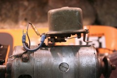
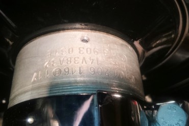
About a dozen years ago, I converted my circuit to 12V, using a rare 90mm generator (ref. VW 113903031E, ref. Bosch 0101206116), and a fitting Bosch 14V 25A regulator (ref. Bosch 0190350049).But that regulator only held by one single screw on top of the generator, and since it was a bit too long, it had to be set askew... And, well, you know my OCD.
So i took a deep breath, a drill press, and drilled a 4.2mm hole in the generator body (making sure I wouldn't drill into a coil inside, obviously), which I proceeded to tap at 5x80 like the other one. Done! I then gave a lick of paint to the regulator, cut 3mm from its back stand, and now it ssits aligned with the generator. Much better!
As usual, since nothing is ever simple, while putting back together the fan assembly, torquing the nut at 6mkg, the expansible washer broke on me... Argh. Ordered a new one from VW Classic Parts (ref. 111119135), yet another week to wait... Damn, restoring these machines requires infinite patience!
...and reassembly!
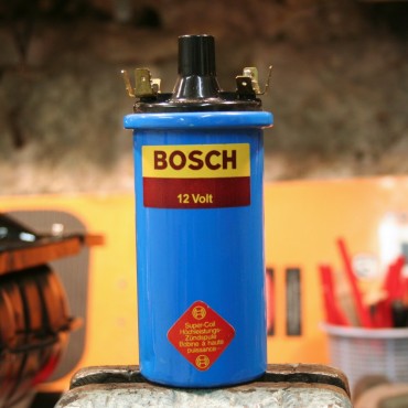
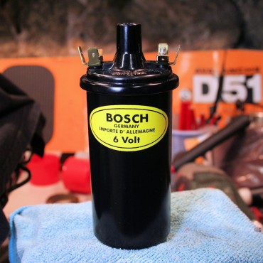
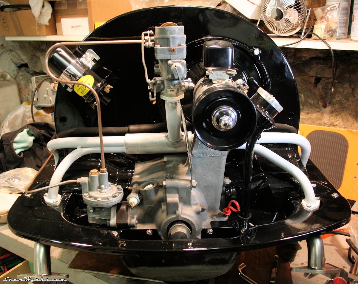
To put everything back together, I ordered a set of stainless steel tinware screws identical to the original ones (mine weren't looking good). The cardboard "seal" between the generator and its stand is glued in place using Gasgacinch.I also give a coat of satin black on the coil (an actual, real blue Bosch one), the generator's pulley, and the oil pump plate (which I had forgotten, and already showed rust spots).
The coil also receives a sticker reproduction to make it look like an old 6V one... That'll make the trick!
After a bit more of fiddling... TADAAAAA!!
OK, almost there now... If the pain in my shoulder gives me some slack, this baby should run pretty soon!
Posted on 15/02/2017 at 18:08
Good Bye Pierburg, Hello Weber!

Conversion Weber 32/34
But in the other hand, when it starts acting, it's a PITA : it's full of vacuum modules, dilatation elements,wax component, in which the cooling liquid goes through... Kind of a Rube-Goldberg machine, next to impossible to fix.
And you guessed it, mine started acting weird, it did not like last April's engine swap (I did write about it at the time already).
Around a decade ago, I had found on eBay Germany a rebuilt 2E2 for a fair price, but unfortunately the vendor doesn't exist any longer. There's a specialist in the UK (Bromyard) that offers complete Pierburg 2E2 rebuilding services, but for a hefty 395 £ + S&H (that's over 500 €), I wasn't too keen on going again with that same Hell-of-a-carb (that being said, looks like that company does a great job).
I also had the option of buying a brand spanking new Chinese reproduction of the Pierburg 2E2 : you can find them on AliExpress, and they will set you back around 100 €. I have to admit, I'm a bit skeptical on the quality of these...
Long story short, I finally bought a Weber DMTL 32/34 conversion kit from EuroCarb via eBay. It's cheaper this way than from national french re-sellers, 324.50 £ w/ S&H (which is 380 €, would have been 455 € w/o S&H at local stores). It's a beautiful kit, very well engineered. Installation instructions are clear, it's almost plug'n'play... Even thought the french traduction is a bit sketchy (and the fuel line clamps are a bit small, but I'm nit-picking).
So now, no more faulty automatic choke, which functioning is a matter of voodoo sorcery, back to basics with a good'ol manual choke!
Installation note : the small bit at the end of the throttle cable cameinto contact with the vaccum element at the back of the carb, preventing the throttle from coming back to idle. I snapped it with a pair of pliers : fixed (on the middle picture below, you can still see the contact point before the modification). I installed the bloody thing on 01/29/2017 and since then : pure HAPPINESS! Starts neatly, acceleration is linear, the engine doesn't die on me any more when cold, more torque at low revs... I definitely should have done this a long time ago!
Posted on 06/11/2016 at 12:59
Elvira : Rebuilding the 36hp, episode 7 : intake manifold


episode 7 : intake manifold
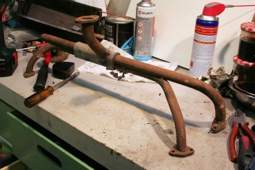
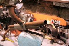
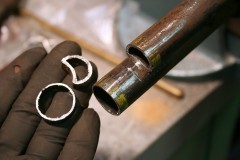
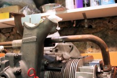
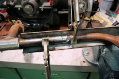
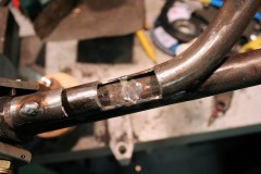
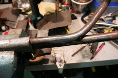
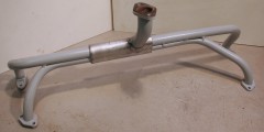
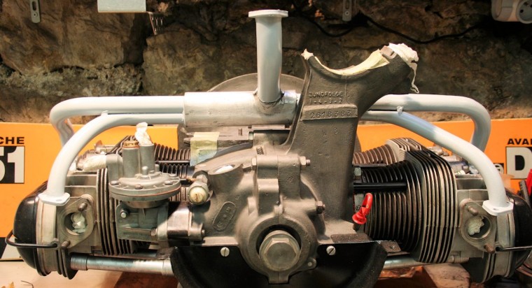
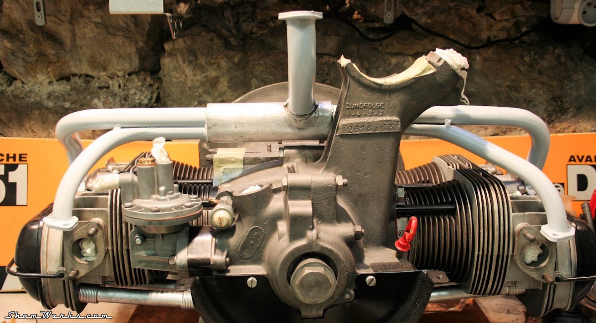
Since I did not want to modify my original 36hp manifold, I found a spare one on LeBonCoin... There we go, I cut using a hacksaw, and I remove the dreadful 6.4mm! I take advantage of the accessibility opportunity to clean the inside of the heater tube, which was in dire need of some TLC. Definitely easier to do this while it's opened like that!
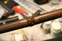
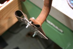
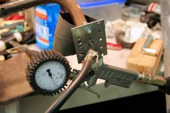
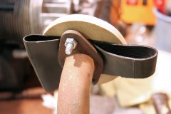
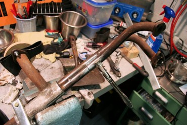
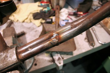
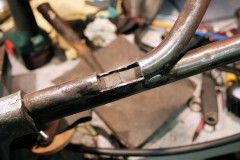
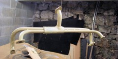
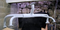
But I don't have access to the cut other side of the tube, next to the first tube I welded. I hoped that a nice clean weld on each side would do the trick, but when I wput it under pressure, it was leaking all over the place. So I got the Dremel out, and cut a window to get to the inside of this cut and weld it from there. I welded the window back in place, and this time it was air tight on the first try! Next step is as usual : sandblasting, 2 coats of rust-preventing primer, 3 coats of paint... And TADAAAAA!! Here's your 6.4mm shorter manifold! Yep, all of the above just for 6 f***ing millimeters! Dayum, you gotta love your compression ratio, right?!
Posted on 25/10/2016 at 00:30
Elvira : Rebuilding the 36hp, episode 6 : Rocker arm geometry


episode 6 : Rocker arm geometry
Since I've milled 3.2mm into each head, the whole engine is now 6.4mm less large...
So, I gotta shorten them pushrods! (and that's just the beginning...)
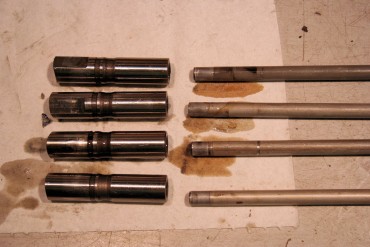
On 36HP engines, contrary to more recent T1, the lifter and the pushrod are one single part...
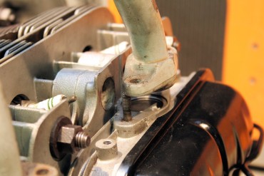
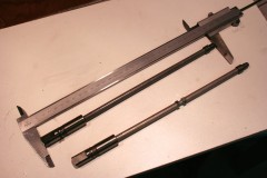
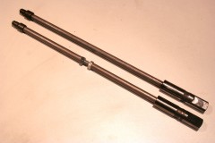
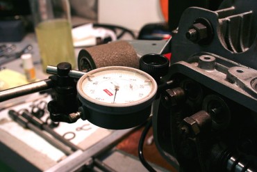
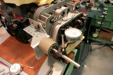
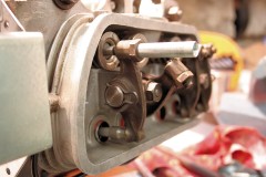
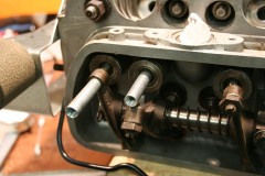
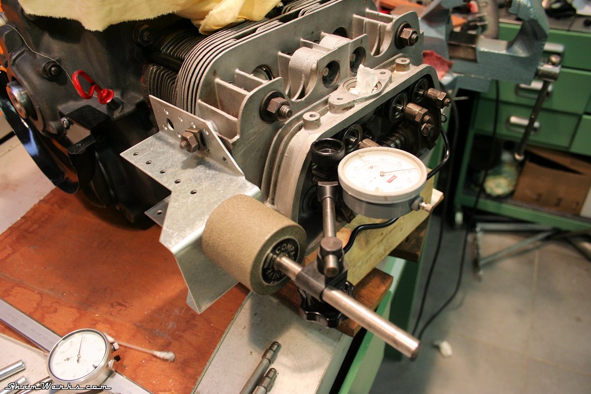
I start by making myself an adjustable pushrod to find out the right length : I grab an old pushrod, cut it in the middle, throw at it a length of threaded rod and a couple of nuts, and I'm ready to rumble. Next, I install a dial gauge to measure the total lift ; I measure 7.76mm at the valve, which is relevant with what I obtained with my camshaft measuring bench (check article here). I then turn the crank until I'm at half-lift (that is 3.88mm) : while in this position, the pressure screw on the rocker hs to be perfectly aligned with the valve stem.
Side note: some of you may argue that this shouldn't be measured at half-lift, but at the angle at which the valve has the maximum linear acceleration, as this is when you get the most mechanical constraints. From a mechanical stand point, that's right... But come on, this is just a 36HP, with chewing-gum valve spring, not a 2.4L with adamantium double valve springs running at 8000 RPM. The half-lift willl definitely but a good-enough approximation!
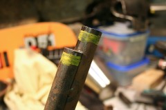
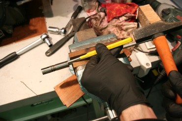
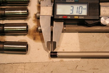
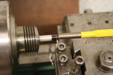
Anyway, I adjust the length of my pushrod, tryin to get the lifter in the correct position... Try, remove the lifters, adjust the rod, put back the lifters... After the 3rd try I had the correct length : 299.2mm, while the pushrods are initially 302.3mm long. That's 3.1mm I gotte take off of each pushrod ; it makes sense, since I got my heads lower by 3.2mm on one side, and 3.15mm on the other. To shorten the pushrods, I first remove the lifter part : it's pretty easy, you jut need to put the rod in a vise (in between two pieces of wood not to scratch it), and give a firm tap with a bronze piece on the lifter. The rods are then lathed down, using a W20 8mm collet. I also remove short of a 1/10th on the diameter over 12mm of length, unless you can't put back the rod into the lifter (trust me, I bent 5 of them trying). I suppose they had a machine at the VW factory that would hold the whole length of the rod to prevent bending.
To make sure the pushrod isn't bent afterwards, I just put it back into the engin case, and make it turn between my fingers : if it's still straight, it will remain centered into the tube! Obviously, don't push it all the way into the case, unless the flat side on the lifter will prevent you from making it turn. Pour vérifier que la tige n'est pas pliée une fois le poussoir : on la remet dans le bloc et on la fait tourner du bout des doigts : si elle reste bien centrée dans le tube enveloppe, c'est qu'elle est droite! Evidemment, il ne faut pas la rentrer à fond, sinon le méplat sur le poussoir empêche de la faire tourner.
Historical side-note
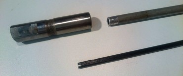
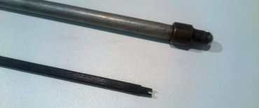
The pushrods on 36HP engines may contain a piece of wood inside (made out of beech wood) : actually that's known to be the only piece of wood in a beetle! (well, if you ignore the convertible tops obviously)My pushrods didn't have that piece of wood inside ; but I had another one (gift from Eric SIMON) which did contain that rod. But the actual role of this rod has never been really established...
(Edit 20161103 : Oops, forgot to add pictures right here!) I've read different theories on the subject :
- To make oil go up to the rockers thanks to capillarity effect : I don't buy it. No pressure, no flow, and the oil would actually drip back into the rod. Nope, not happening.
- Pumping effect due to the wooden rod going up and down into the pushrod... I don't believe it either, there's an actual oil pump pushing behind, I don't see how that would work.
- To dampen the vibrations and limit distribution noise by absorbing some of the harmonics : well, why not, could be.
- To limit the oil volume in the push rod. Thus limiting the weight of the pushrod, making the whole distribution lighter. Plus, upon starting the engine, you'd have less volume to fill up, meaning faster pressure build up. That could make sense ; the flow is anyway limited by the hole diameter on the lifter and on the rocker side : no actual need for the pushrod to be filled up with oil.
That's all folks, to be continued soon!
Posted on 26/09/2016 at 20:14
Krapo Bleu : Recaro and Gearbox linkage

Recaro & Gearbox linkage
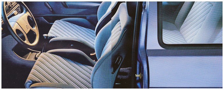
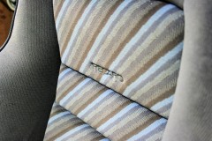
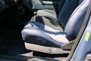
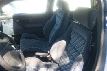
My Golf is a 10 Millionth Edition (or "Champ" in France), and this limited edition had several very specific options at the time, one of them being the fabric used for the upholstery, a stripped blue that's on no other model (pictured below, from the period leaflet).
Well, actually, this was what I thought, for almost 20 years, until 2 years ago...
I then found out that in 1989, a limited edition of Jetta (the "GLI Helios" edition), of which only 1500 units were made, exclusively for the american market, had also received the very same fabric on their seats.
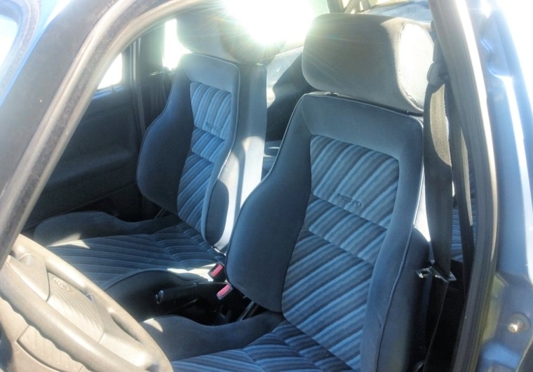
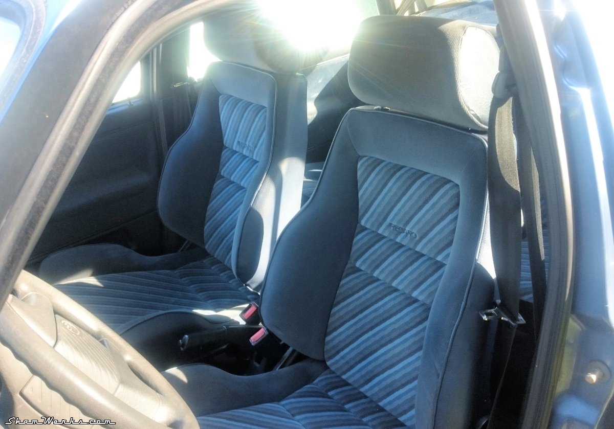
With a major difference though : it featured very desirable Recaro front seats!
Needless to say, I started hunting for a pair of those, but they're rare as hens teeth, and whenever an ad is published, it' always in the US, with prohibitive shipping costs.
Being my usual stubborn self, I kept looking, for almost 2 years...
Until march 2016, when an auction pops up on eBay UK, a stone's throw away from one of my in-laws! God Save the Queen!
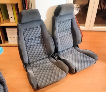
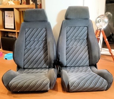
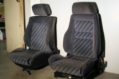
I won't bother you with the details of the organisation set up to retrieve and ship the seats to southern France, but here they are, even nicer than I expected them to be!
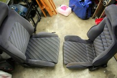
(yeah, OK, spending that much time and energy for a pair of bloody seats, I know I have a problem, leave me alone!) Here's the difference between the original "Sport" seats and the Recaro version : But how the Hell these parts, exclusively made for the US market, made their way to Europe?
Actually, around a decade ago, a US soldier dispatched to an american air base in the UK, decided to import his Jetta Helios... He ended up selling the car there, but unfortunately it got wrecked and sold for parts. The seats got bought and stored for the next 9 years, until their owner decided to part with them. They got attacked by rodents in the meantime, but were neatly fixed by an upholstery shop, with a leatherette matching perfectly the original one.
You know what happened next...
Let me tell you that there's probably not more than a handful of those in Europe! (I only found one German guy who installed a pair in his 10 Millionen)
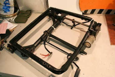
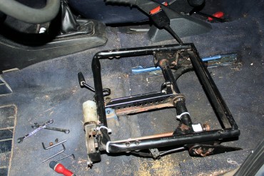
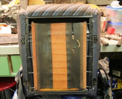
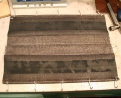
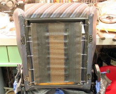
I still needed the railings to install them... I found'em in Poland (damn, eBay is a hard drug), a complete G60 set with electric adjusting (too much?
Not that easy to replace though, as it's very tight! My solution finally was to grab each hook with vise-grips, then use a clamp to pull the grips towards the edge of the frame. And.... TADAAAAAAAA!
I still have to install a bit of wiring and a 20 amps fuse to use the electric adjustment thingy, but I can already enjoy the bloody things! Dear Martin, thank you so much for your help securing the Glorious Seats!
Bonus : Gearbox linkage upgrade
Keeping on track with the improvement of both user experience and reliability, I decided to make a big update on the gear selector linkage.The original bushings and links, made of plastic, end up wearing and breaking up (I think I changed mine at least 3 or 4 times). You then get a good 10cm end play on the gear stick, no matter if you've selected a gear or on neutral! You can still use the car if you're used to it, but forget about "race" driving. In the other hand, it's a pretty good anti-theft device!
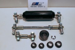
Long story short, I ordered a "Smartshift 2" kit from USRallyTeam, which replaces all links with Unibal joints, and all bushings with Delrin-made ones (POM). No more end play!
I installed the kit on January 30th 2016, but it left a mark (literally) : as I was cutting off one of the joints with an angle grinder, I made a wrong move and sent the cutting disc into my left thumb. Cut down to the bone (got a nice gouge in it), tendon and nerves ripped... #ERsaturdayNight
Anyway, I spent a night at the hospital, but at least the kit is installed, no more end play in the stick, it feels great!
In the picture below, you can see the ugly original plastic joints and "ball", that usually wear off and break
Second picture is the kit form USRallyTeam : now we're talking!
I'll spare you the picture of my post-surgery, Frankenstein-like thumb...
In short, not exactly a plug'n'play kit, but a great improvement nonetheless in the end.


