36hp, part 3 : Closing the engine
FOUR YEARS! Four years I've been waiting for the stars to align so I could finally close this case! FINALLY!!!
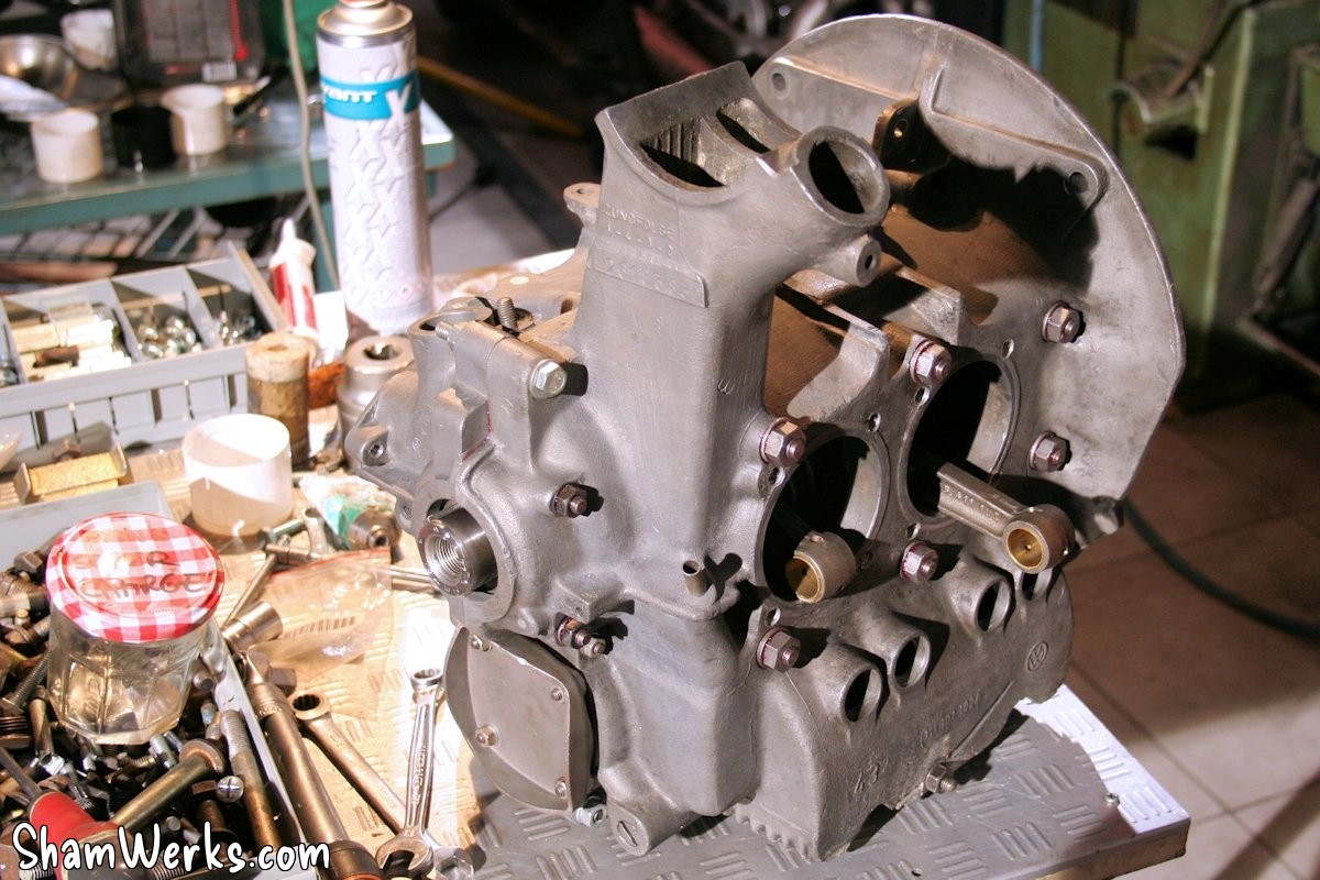
Engine crankcase
Contrary to what I announced in my previous post (in March 2012...) on the subject, the metrology of the crankcase was in fact not so good.
After taking it apart again with a fresh perspective and my new equipment, I realized the crankshaft bearings were out of spec due to ovality. Not by much, but I wasn't going to reassemble the crankcase like that, with all the parts I have; it would have been a waste: NOS connecting rods, NOS piston pins, NOS crankshaft bearings, NOS connecting rod bearings, NOS cylinder sleeves, NOS cylinder tins (!), Joe Ruiz "Okrasa" camshaft...
So, I sent the case to Feller for a +0.5mm crank bore. And then I had to find oversized bearings (too bad, I had some NOS VW ones in the original size, still in their box!)... Not an easy task for the 36hp! Classic-Store has some in stock, but they're poor quality (Sintermetal, made in Argentina), even they recommend against using them! (" but at least they exist ")
After 18 months of searching, I finally found them in Germany. NOS VW, €150 a set plus shipping (ouch!), but oh well, not much choice... It's already the end of 2013, and in the meantime I've started working on the KG engine. The 36hp then waited patiently on its shelf...
But it's over, time to close the baby! 😁
In January 2016, I went to Laurent's (Dangerous - thanks, mate!) to close up the crankcase: he's more experienced than me, and two heads will be needed to check everything during assembly. That said, we still managed to forget the cylinder tins during cylinder head installation... 😁
This also means slightly fewer step-by-step photos, as the lighting conditions in his workshop are not ideal.
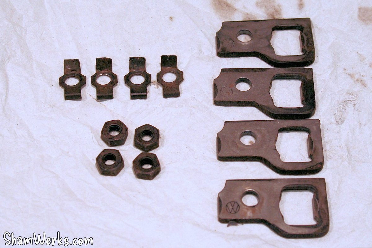
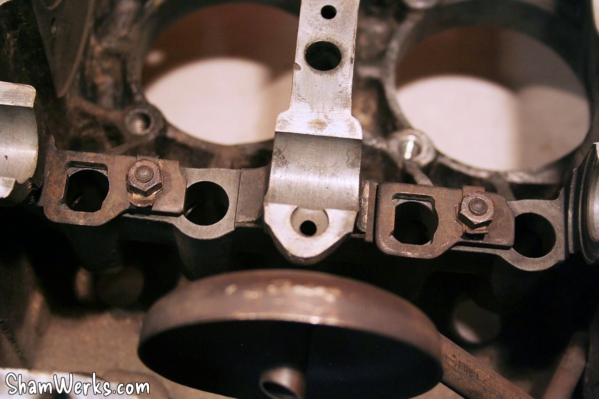
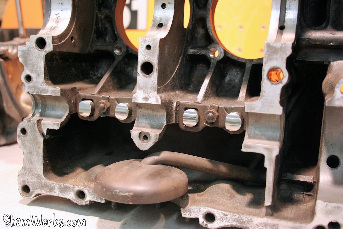
But before I forget, I put back the small guide plates for the lifters (which have a flat side and don't rotate on a 36hp). I tighten them lightly with a drop of threadlocker, and fold the locking tab back onto the nut. It's done a bit by feel; the tappet should slide smoothly with very slight play.
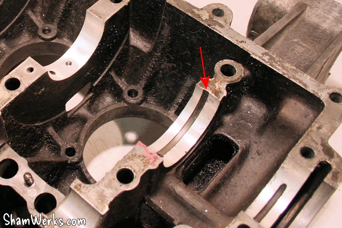
Following that, I resumed work on the oil gallery at bearing #3: on the 36hp, the oil passage is machined into the block instead of the bearing, and the re-machining of the shaft line has seriously reduced its size. I deepened it a bit with a Dremel, on both crankcase halves.
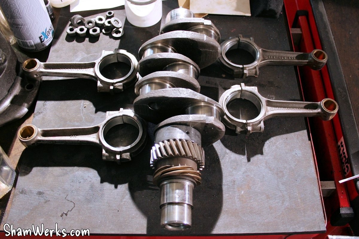
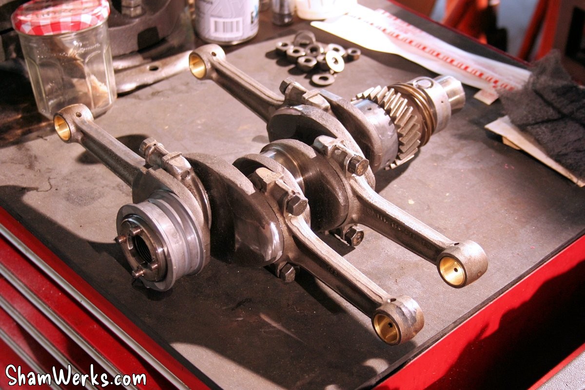
Connecting rods
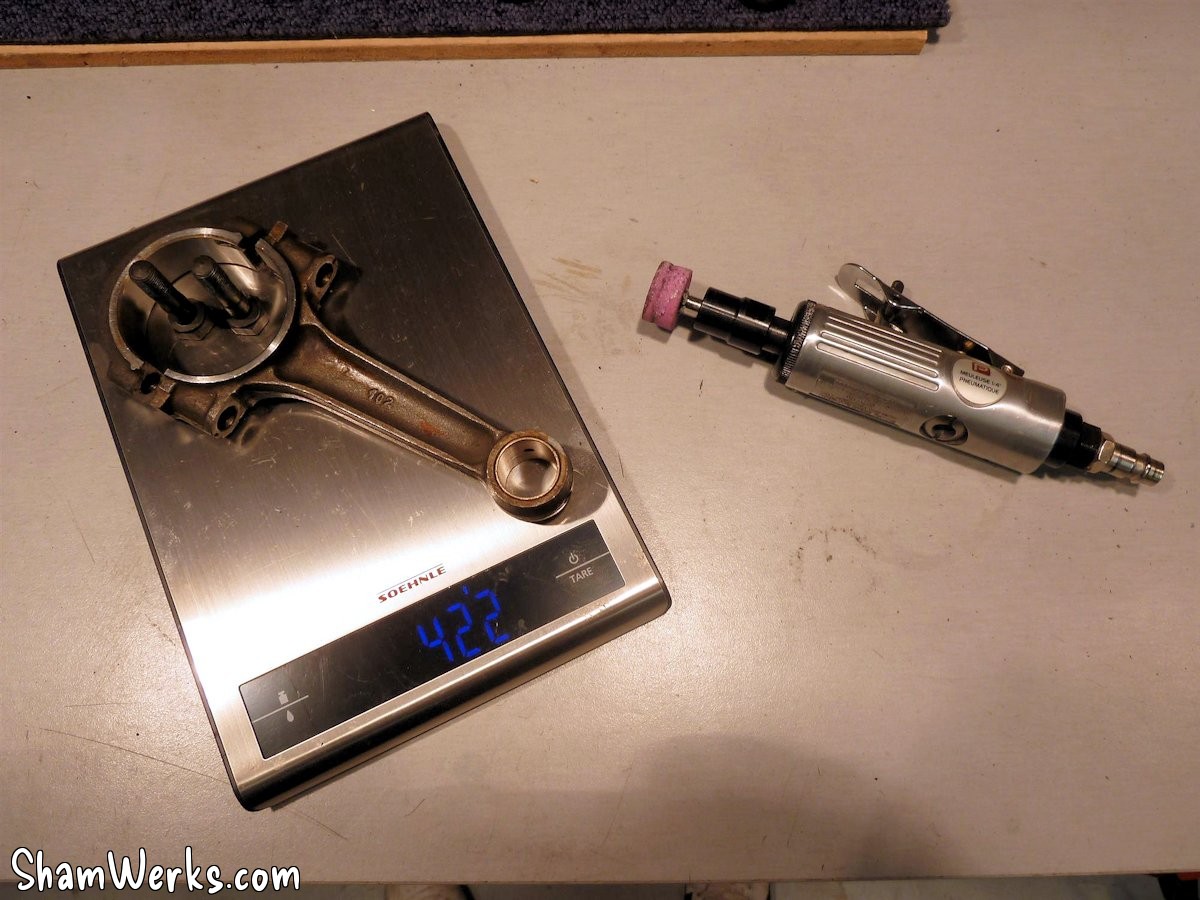
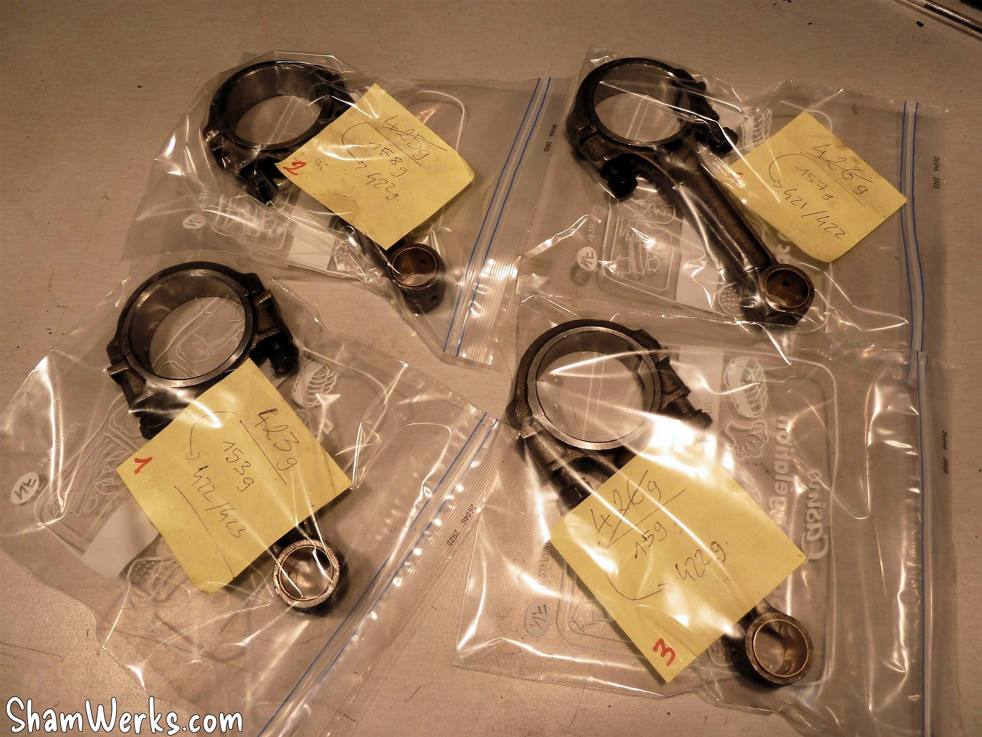
The NOS connecting rods are balanced, roughed out with a pneumatic grinder, and finished with an electric file: I have a 0.7g difference between the heaviest and the lightest.
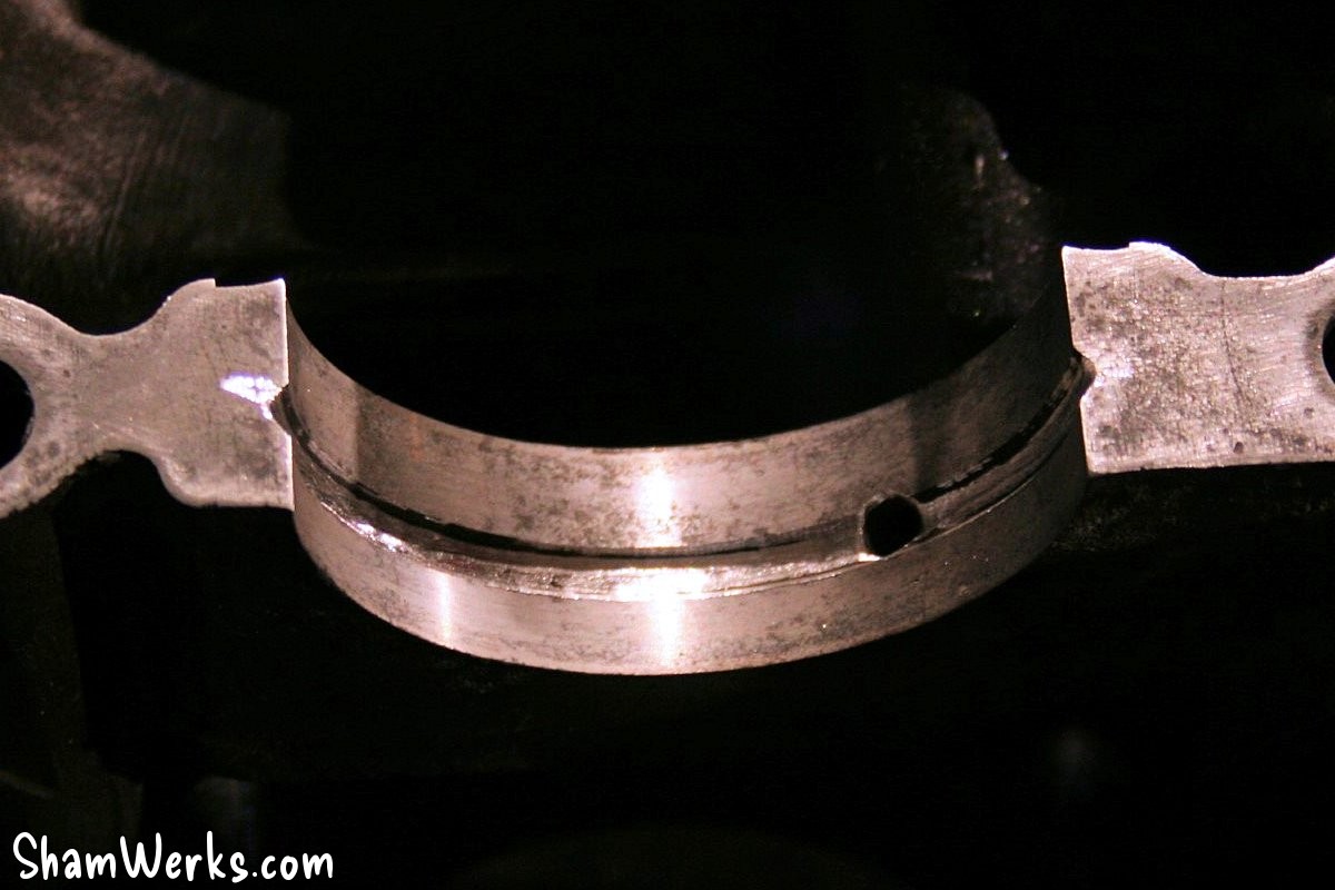
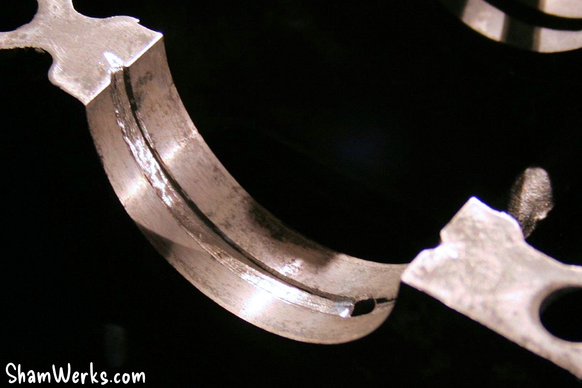
Their bearings (also NOS) are deglazed with a piece of worn Jex pad (with oil), installed, and the play with the crankshaft journal checked with Plastigage.

The crankshaft is first fitted with the camshaft and distributor gears, then the connecting rods are mounted on it, tightened to a torque of 5mkg (according to the RTA and the workshop manual, surprising: 3.5mkg on T1!), and de-stressed (a small tap with a hammer and a bronze drift to release the stresses related to tightening).
During assembly, I lubricate the crankpins with Wynn's Supercharge to ensure lubrication during assembly and until the first start. Since it's very viscous and sticky, it won't run off like oil...
Cylinders / Pistons
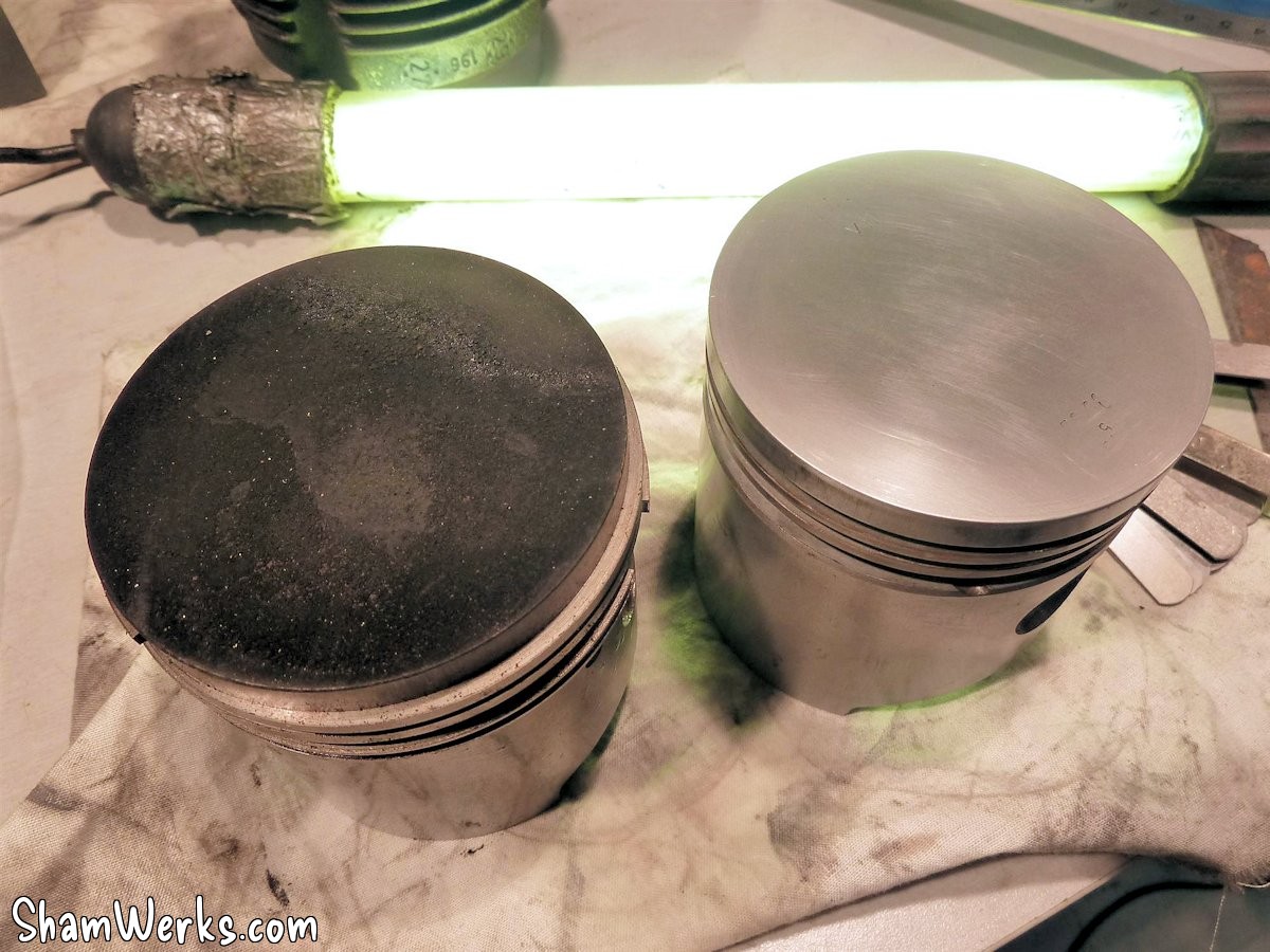
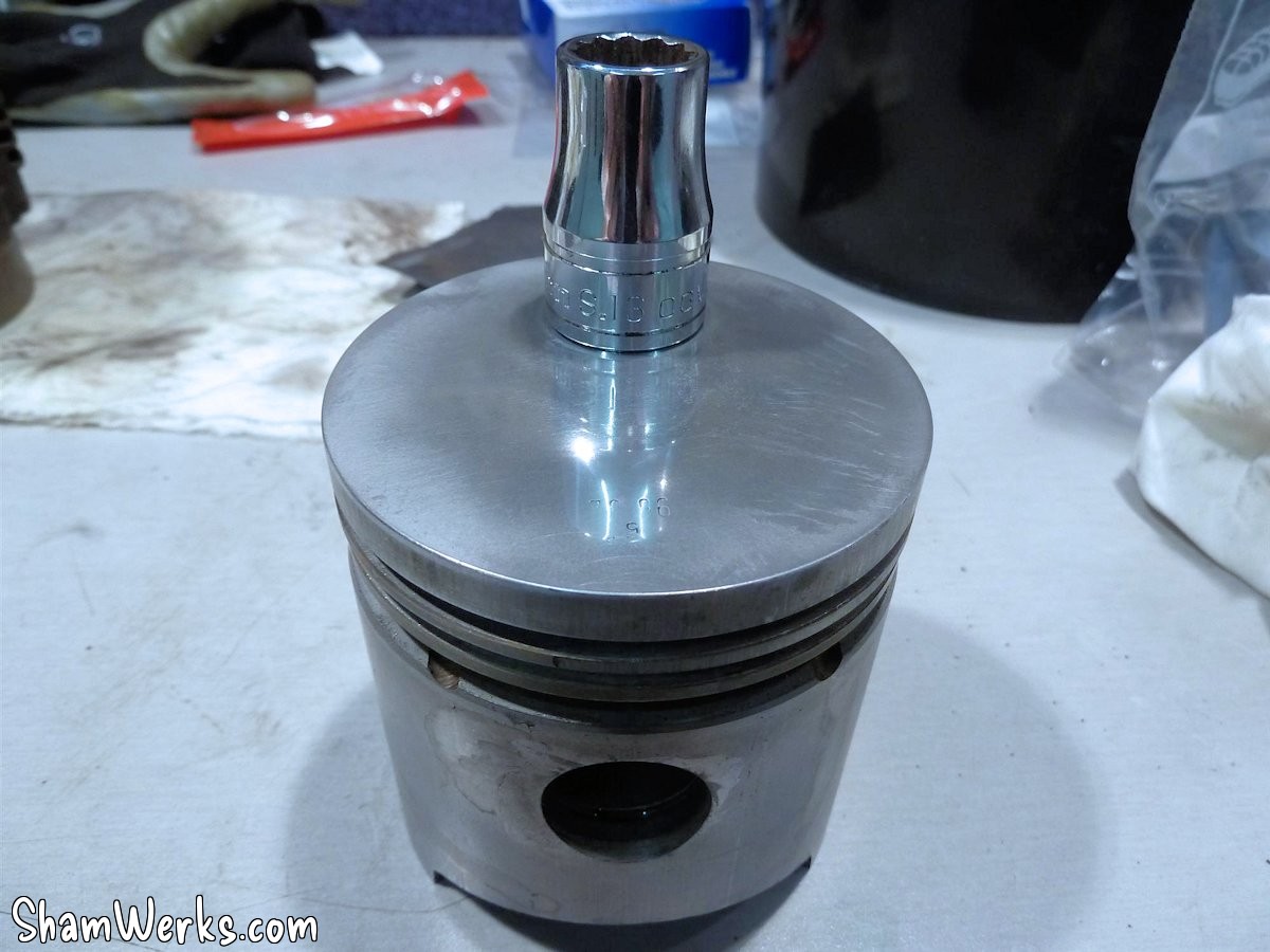
The piston heads were polished on a surface plate to limit heat transfer.
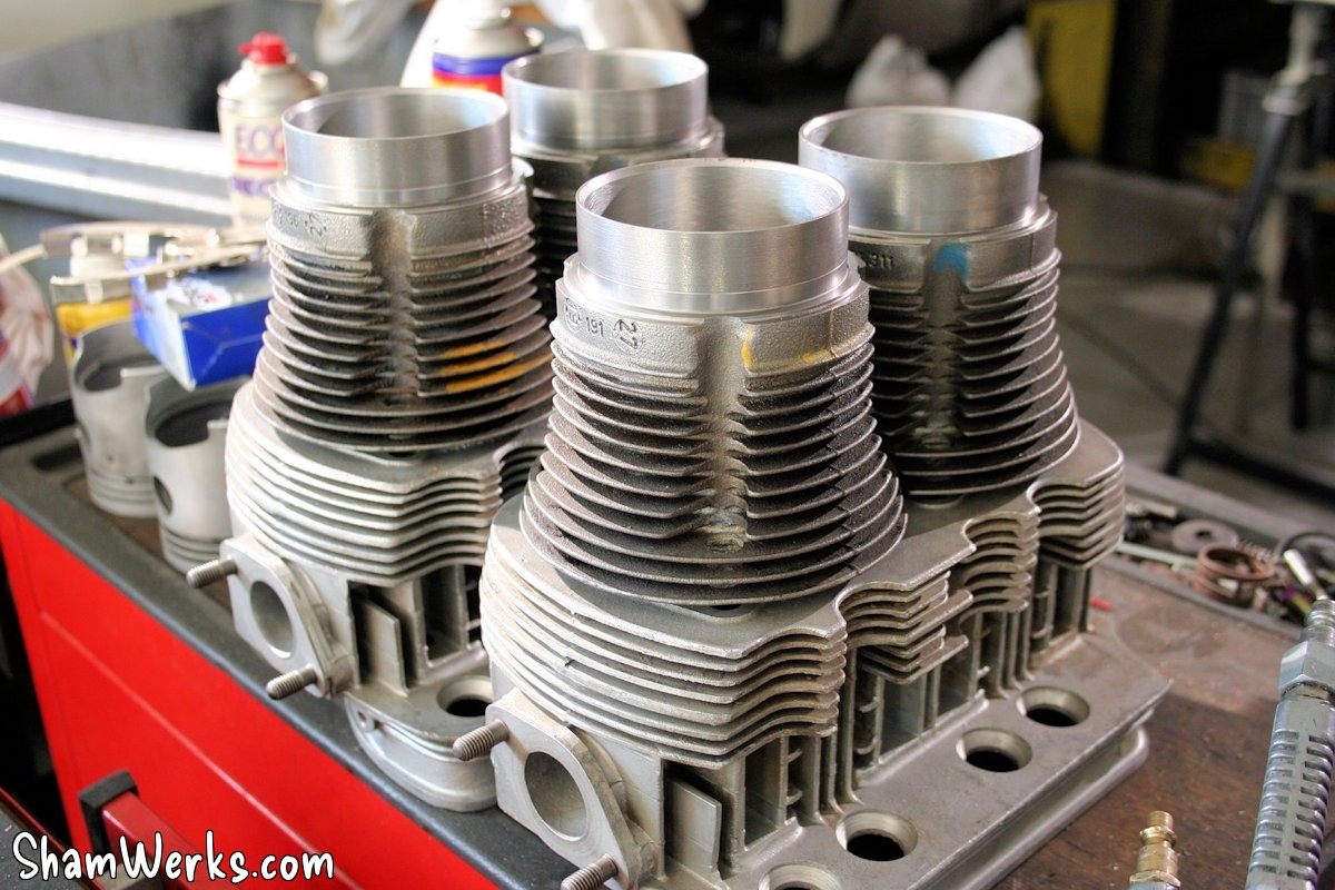
The cylinders were checked at the same time as the pistons: everything is within spec. Clearly the kit has very low mileage: personally, I've only done 2000km max with this engine, I assume the cylinders/pistons were brand new.
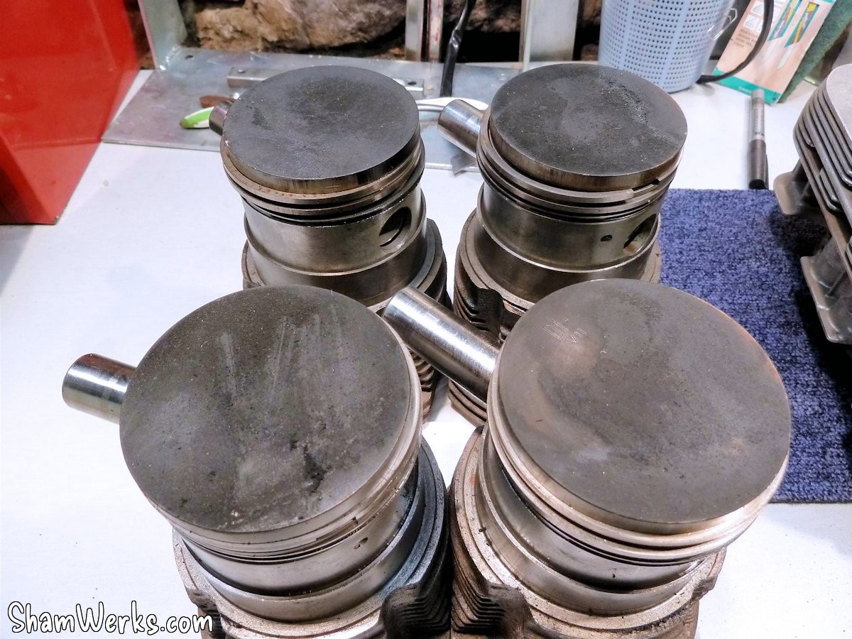
In short, the cylinders are simply cleaned and deglazed (honed), and are declared fit for service.
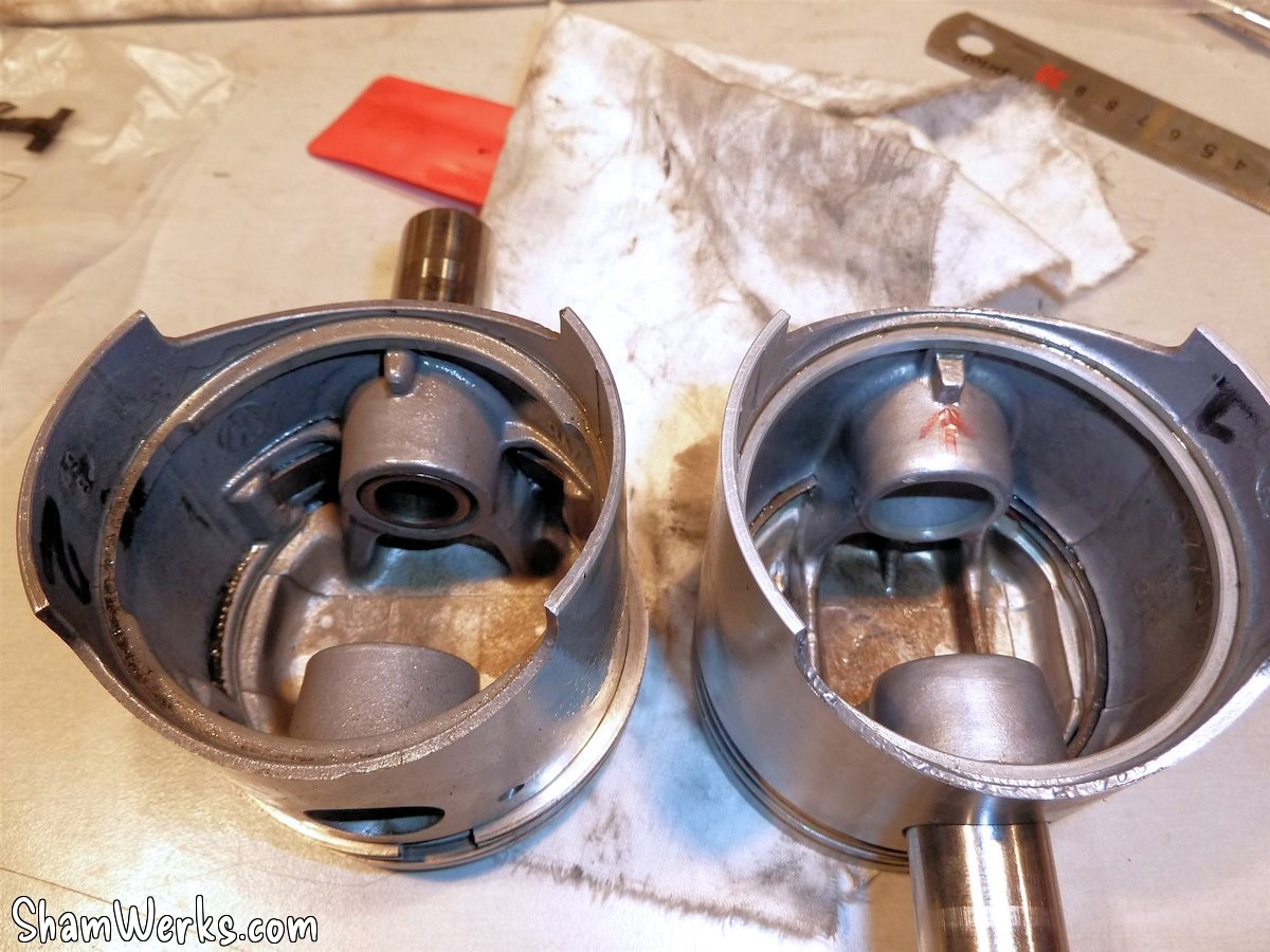
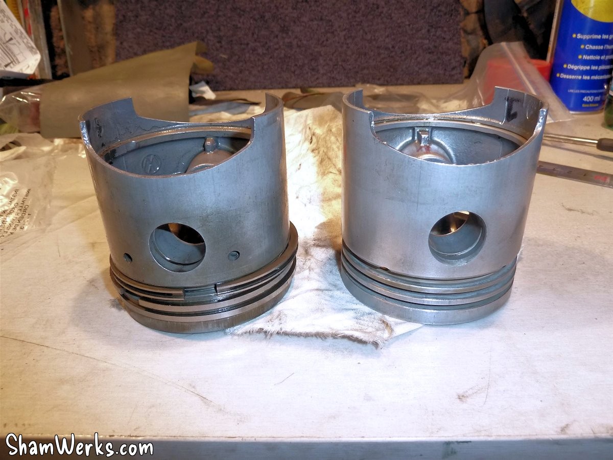
The pistons are nicely prepared: a small chamfer on the bottom of the skirt (with an electric file: great tool, I need one!) to help the creation of the oil film, broken angle at the head (gently with 800 grit sandpaper), and weighting (not easy, 2 different foundries, I had to resign myself to having two heavier and two lighter ones, each pair placed in opposition 2 by 2).
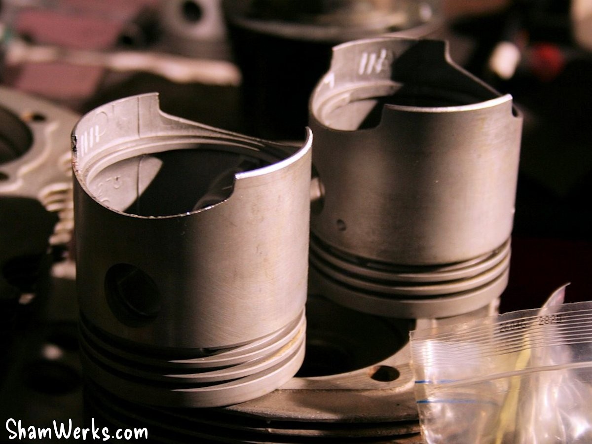
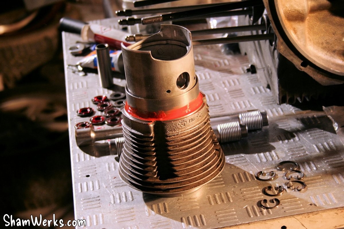
I check the piston ring end gap: the workshop manual specifies between 0.35 and 0.62 mm, mine is 0.35 mm tight on all 8 sealing rings, perfect. I install them gently using the ring pliers, and oil everything well; we make sure the " top " marking is facing upwards, we stagger them taking into account the orientation towards the flywheel (two oil scraper ring openings at the top, offset by 45°, two sealing ring openings at the bottom at 120°).
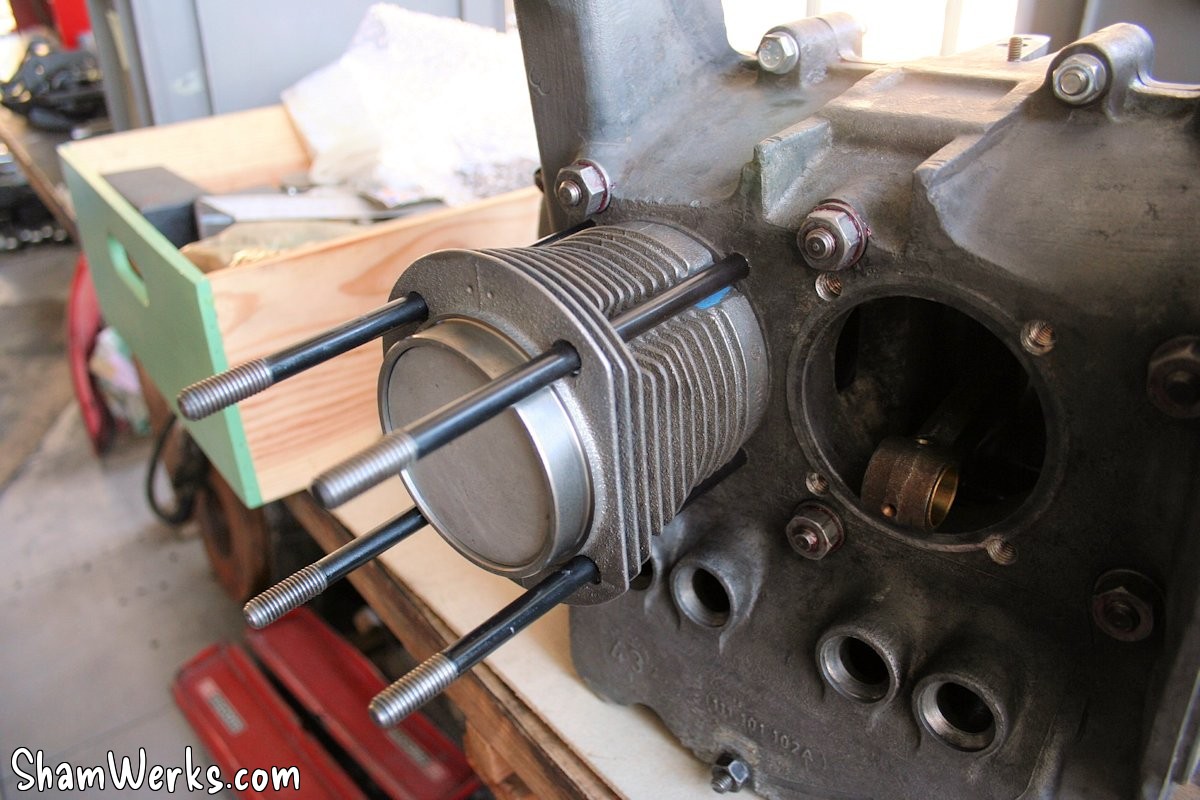
Finally, the pistons are fitted into their respective cylinders with a ring compressor, and plenty of oil.
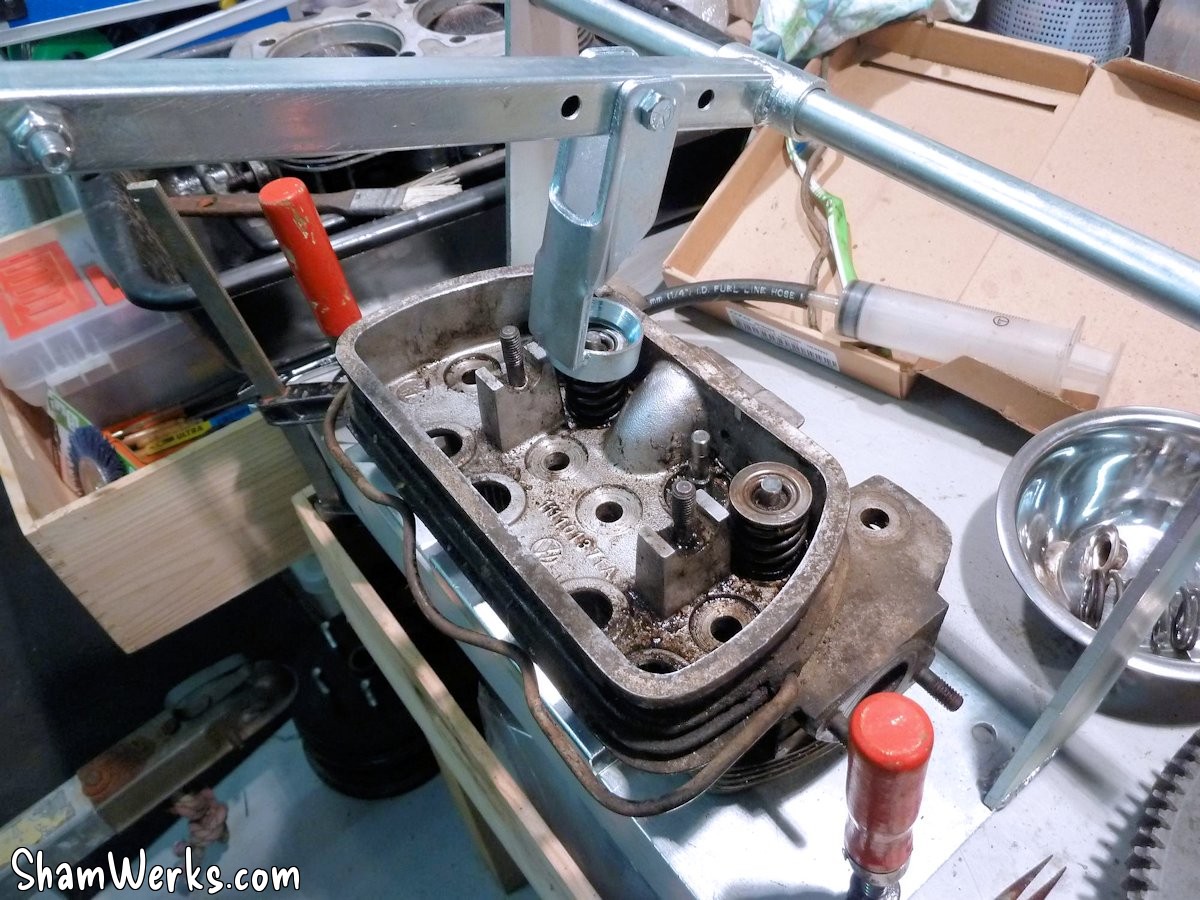
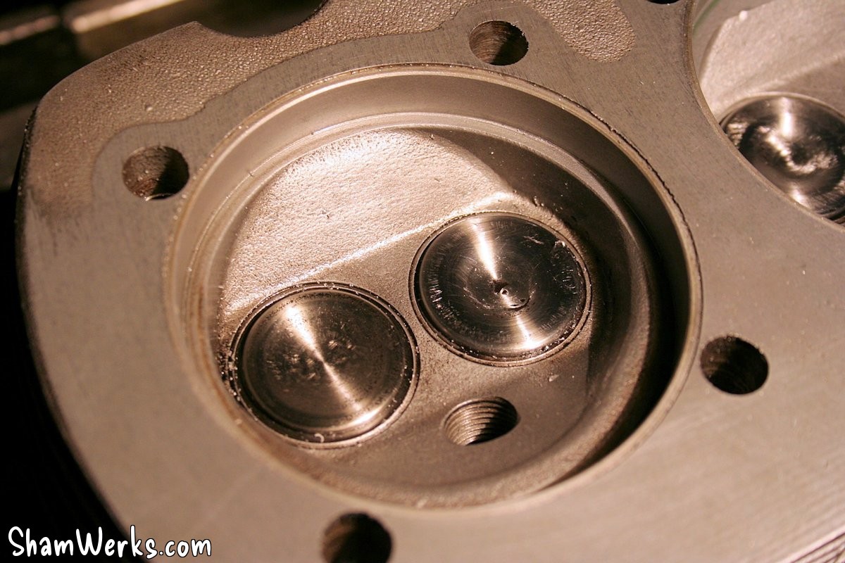
Cylinder heads
A lot of work went into the cylinder heads I found in Valence...
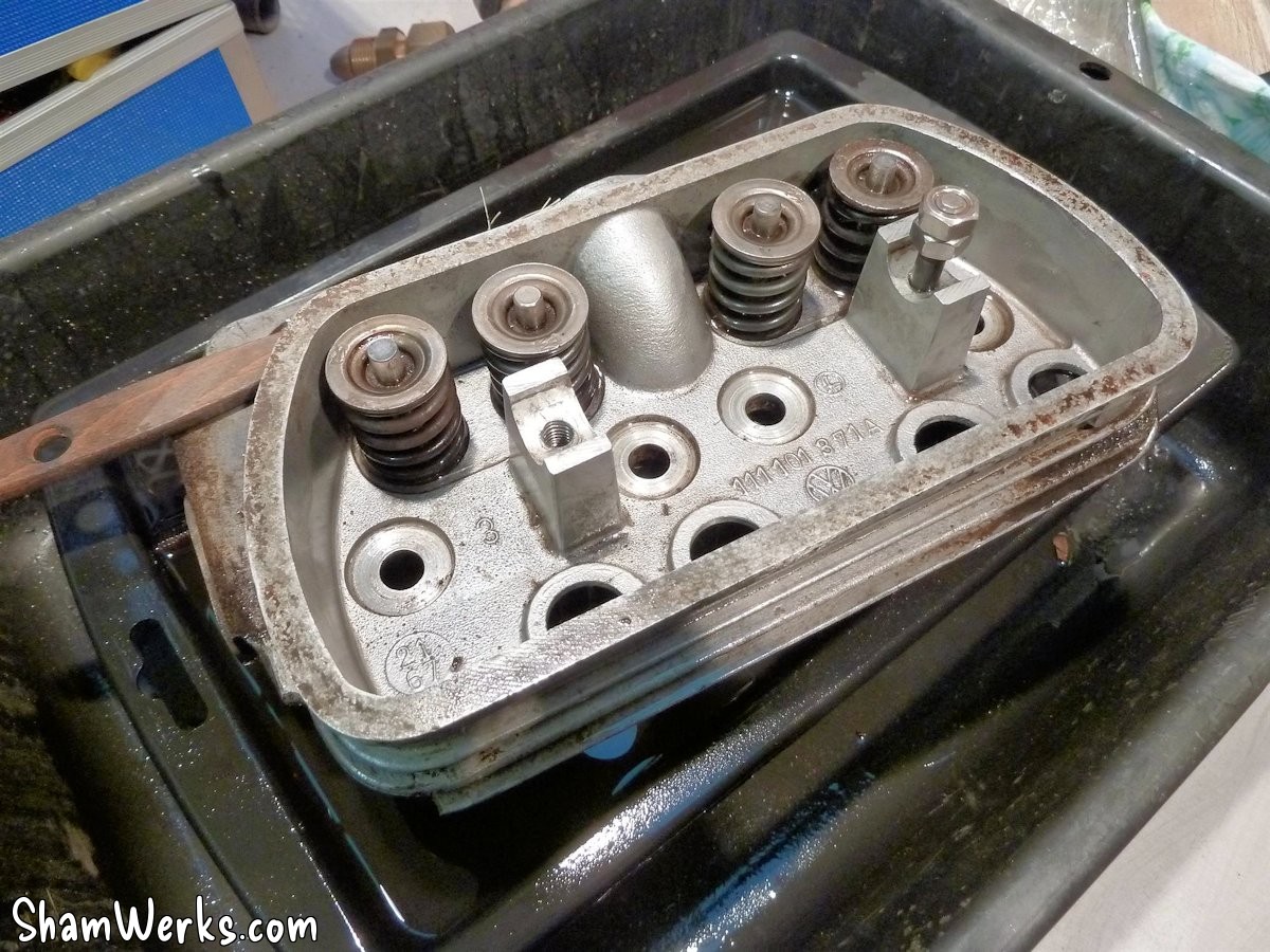
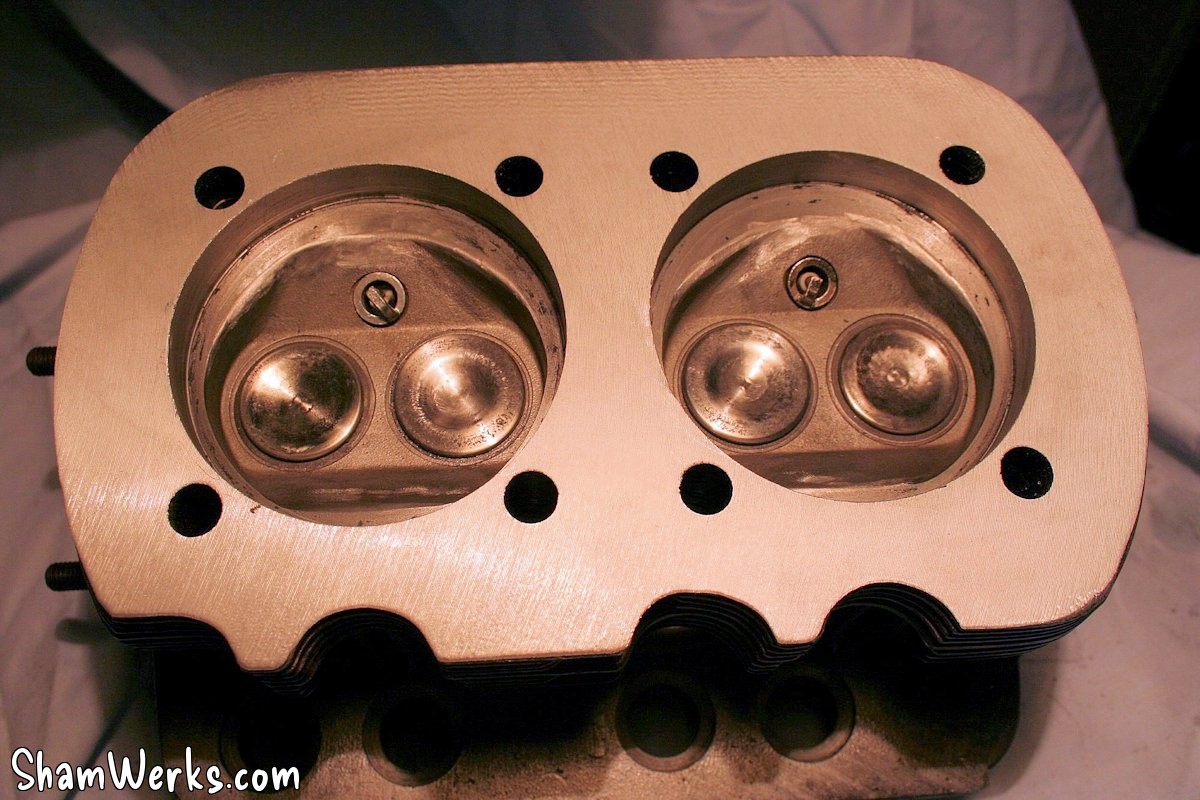
After a thorough cleaning with white spirit, I micro-bead blasted them to get a better look. No nasty surprises, just a tiny bit of a fin broken, nothing serious; and most importantly, no cracks. Jackpot!
By the way: it's best to plug the valve guides for micro-bead blasting; a good tip for this is using disposable foam earplugs! 😉
They're clean, but well... there's room for improvement. The stock engine isn't exactly a powerhouse; if there's a horsepower to be squeezed out here and there, why not take advantage of it? And the cylinder heads on a VW engine are the heart of the matter...
So let's roll up our sleeves and get going!
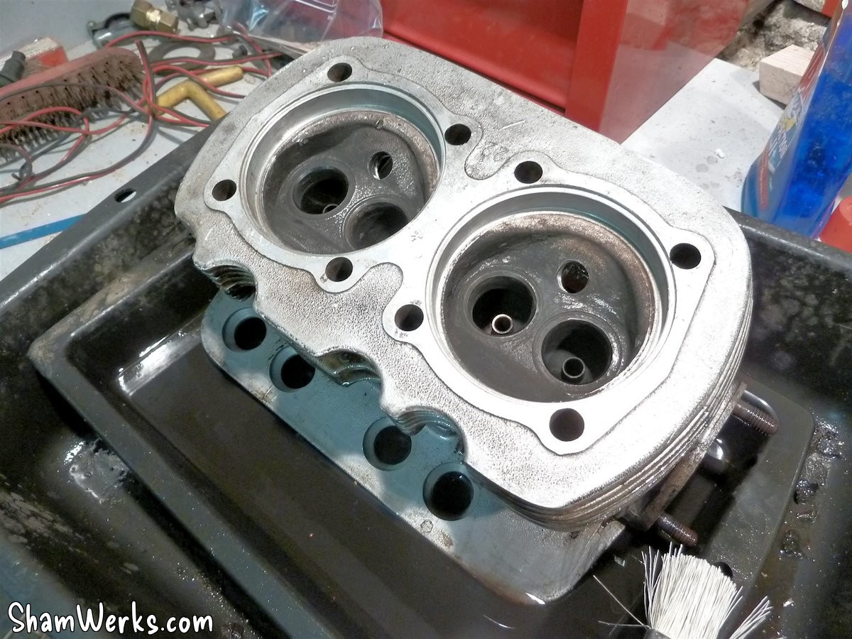
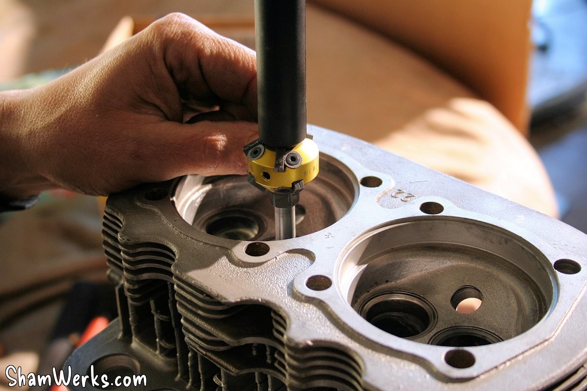
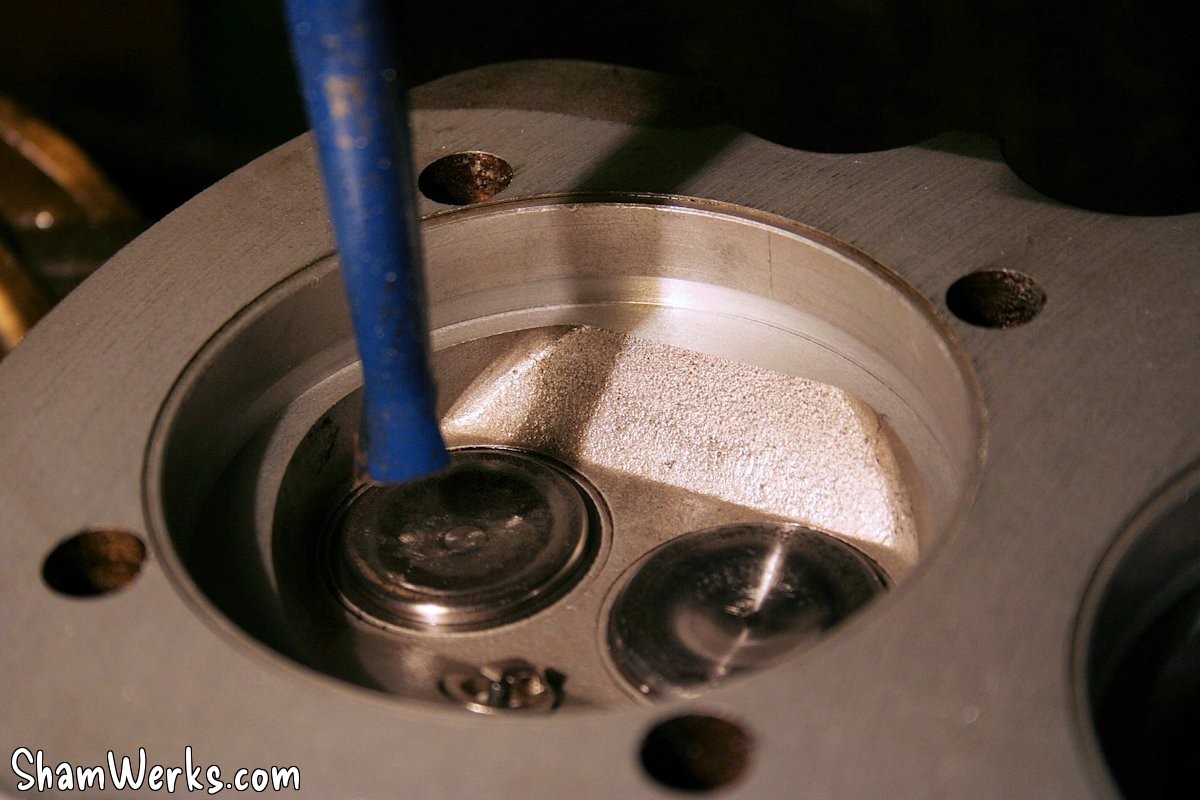
To begin with, the valve seats are reworked at three angles to improve flow (there is an ugly original step): you have to go very gently, there's not much material to work with.
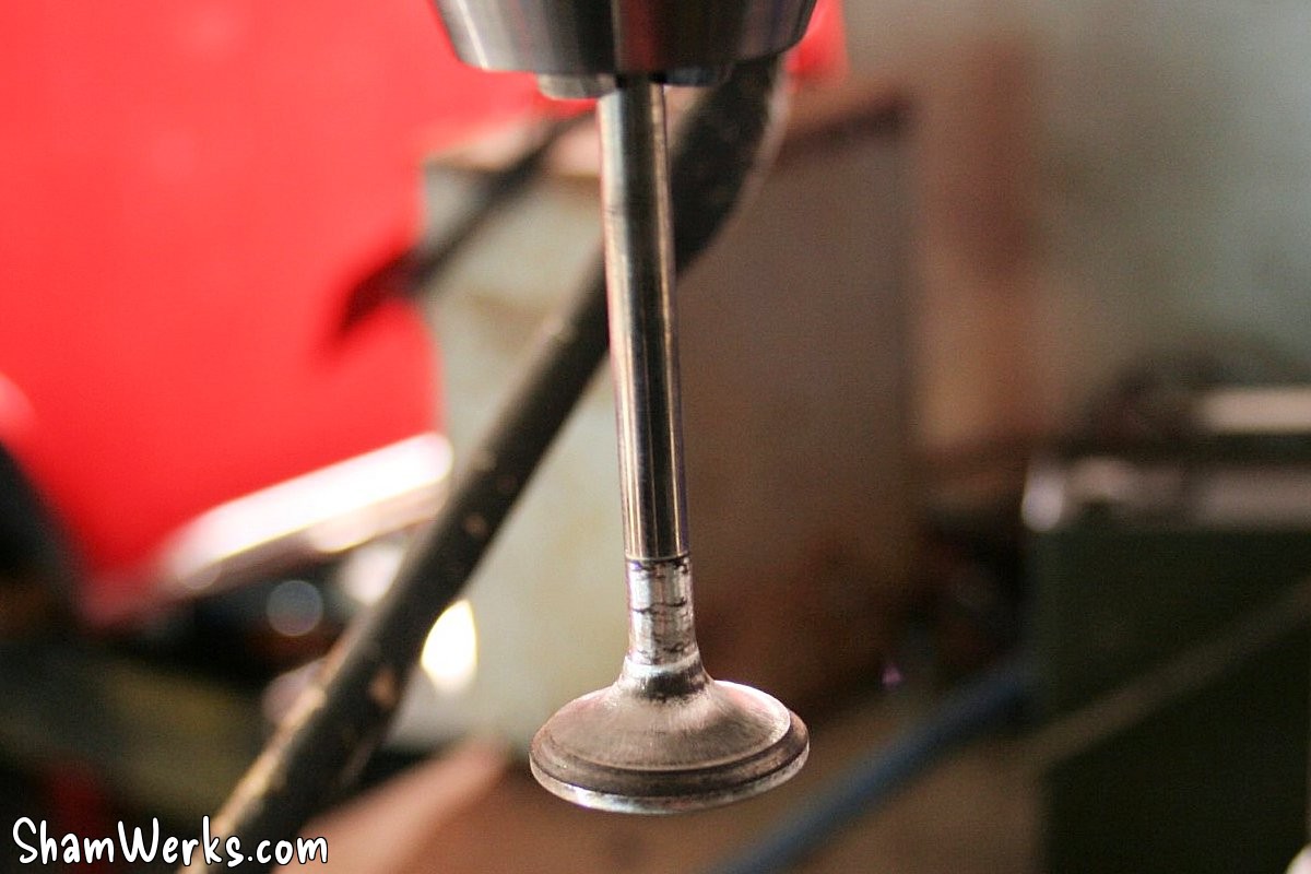
Next, the valves are cleaned and slightly modified: mounted on a drill press, and reworked with an electric file. Smoothing, the head slightly reduced to remove the boss... The goal is always to improve the flow; very gently still, there's not much material to work with.
The valves are lapped on their seats, and the valve stem retainers are reduced (at the contact surface, to fit well on the valve; the keys were touching and therefore had play on the valve).
Then the head conduits are slightly reworked, to remove the steps, foundry marks, seat/conduit alignment, etc... Dremel and pneumatic milling machine, and we smooth everything out.
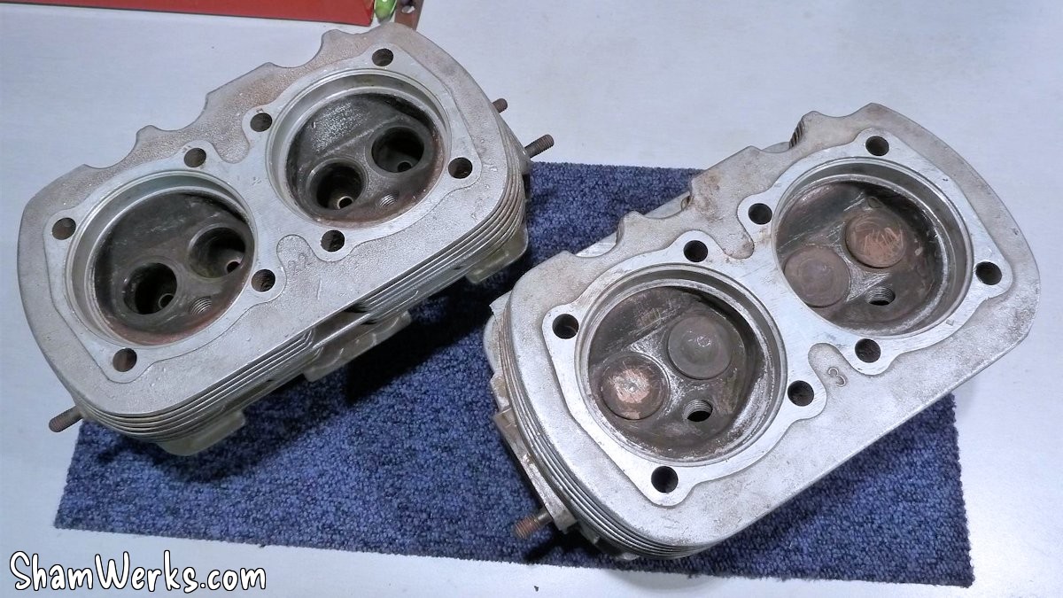
Next: originally, the compression ratio was 6.6 (according to the RTA), which was ok with the fuels of the 60s, but frankly outdated with our Super 98: an 8.5 would be better, no risk of knocking, more watts and better performance.
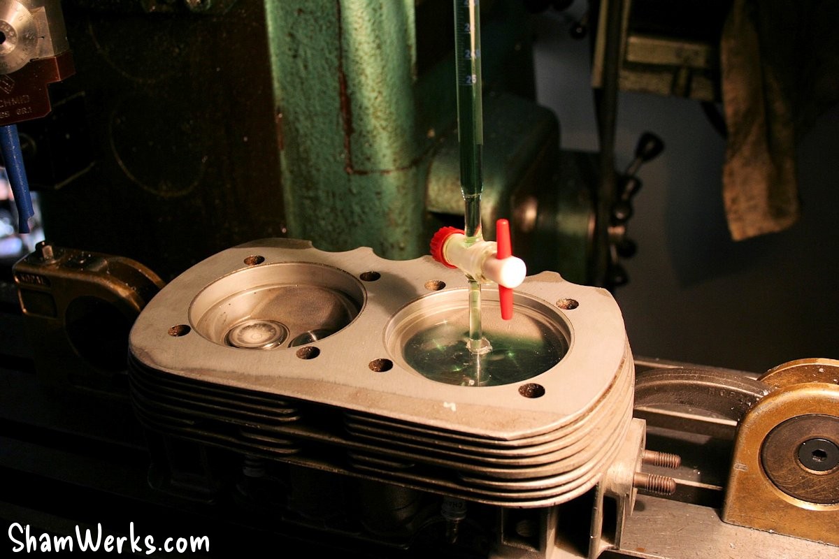
So I measure my deck height (0.88mm) and the original chamber volume ( 48.75cm3 ): I get a CR of 6.64, which corresponds well to what the RTA announces.
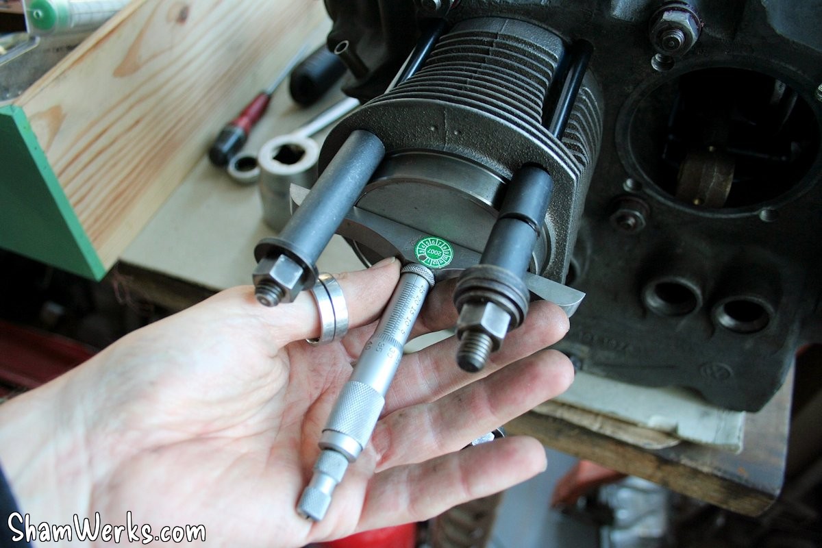
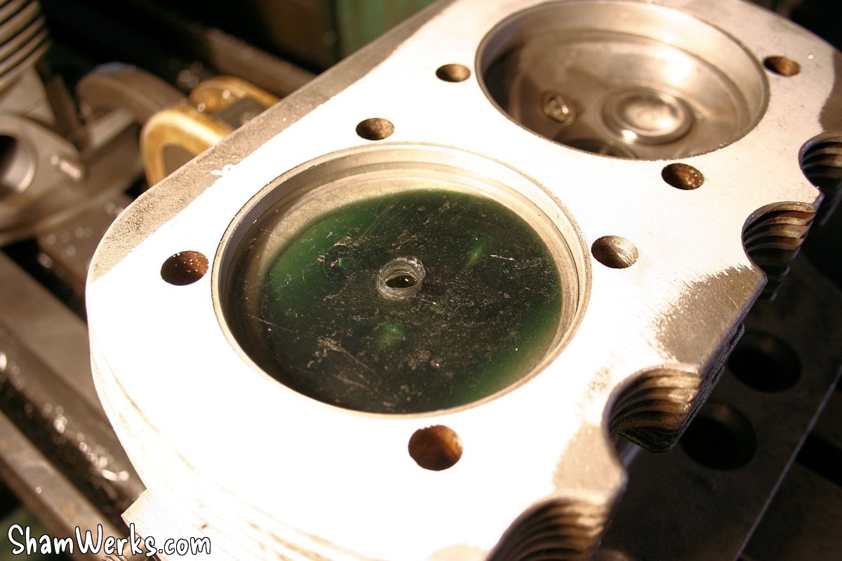
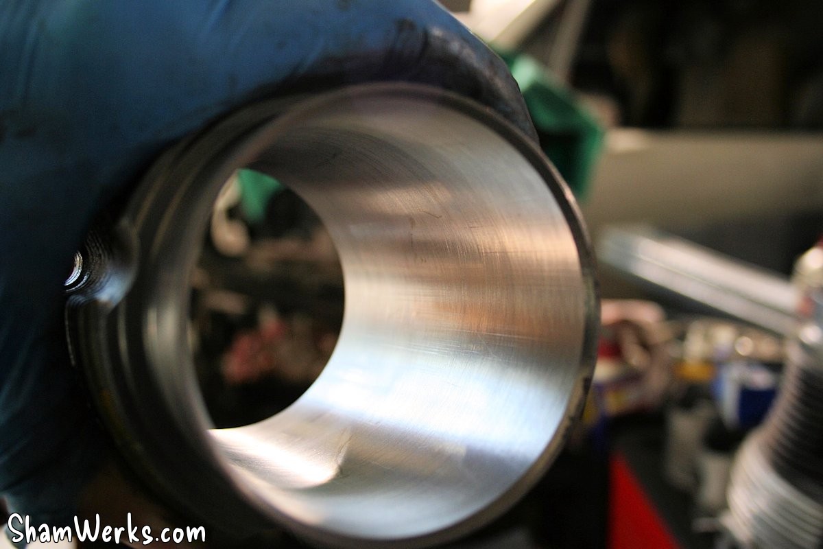
To increase this CR, you have to decrease the volume of the combustion chamber, and for that you lower the cylinder barrel into the cylinder head, regularly checking the volume obtained, and recalculating the CR (on this subject, there is a great calculator on F4E for this...).
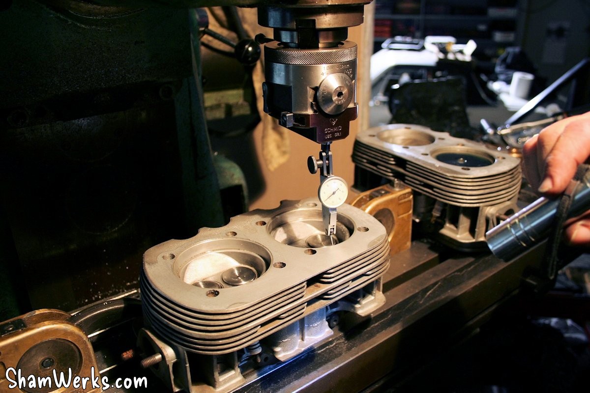
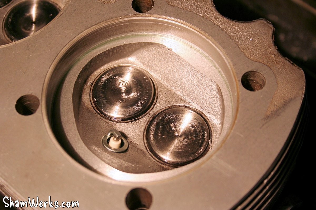
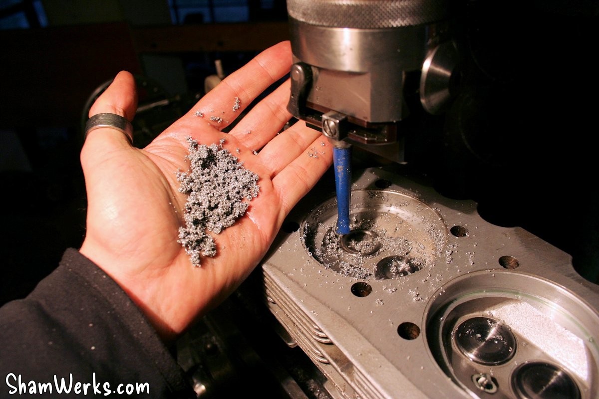

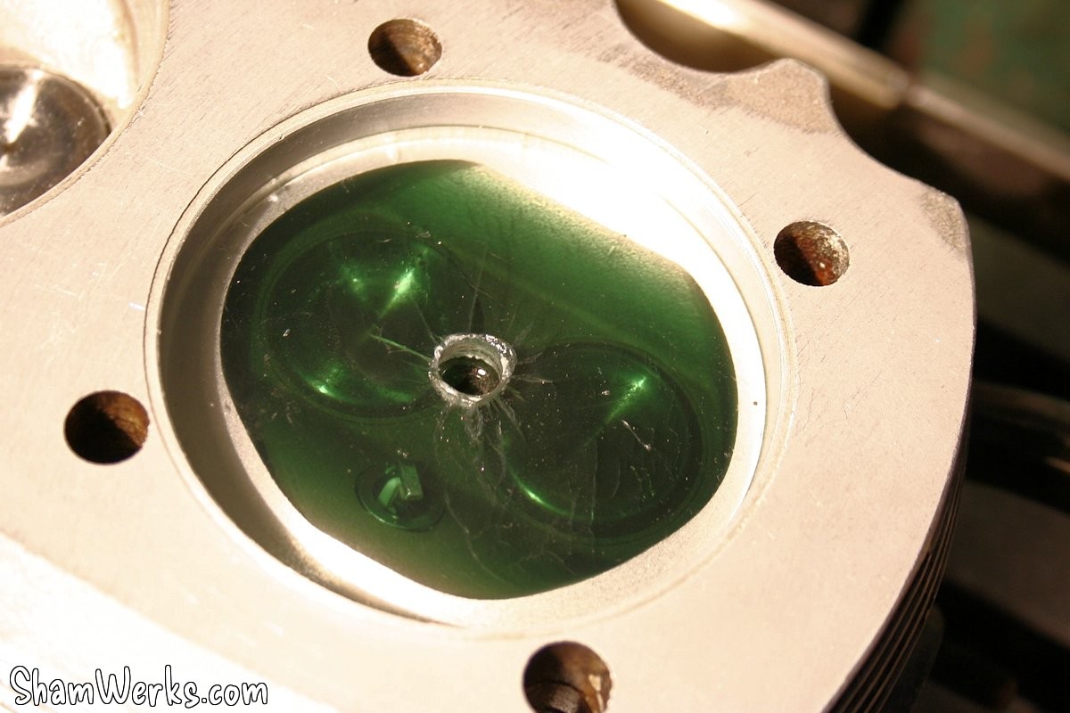
Between centering with a comparator, adjusting the boring head (automatic, a nice tool), and taking regular measurements, it took a day and a half of work.
In the end, by going down 3.2mm, we arrived at a chamber volume of 35.6cm3 , and therefore an RV of 8.51. Woohoo!
The same punishment was applied to the other cylinder head, which was lowered by 3.15mm to have the same chambers.
Obviously, before embarking on this modification, you must check the valve lift to ensure they do not touch the pistons at full lift... In my case, no problem, I must have at least 5mm left, I'm well within the limit.
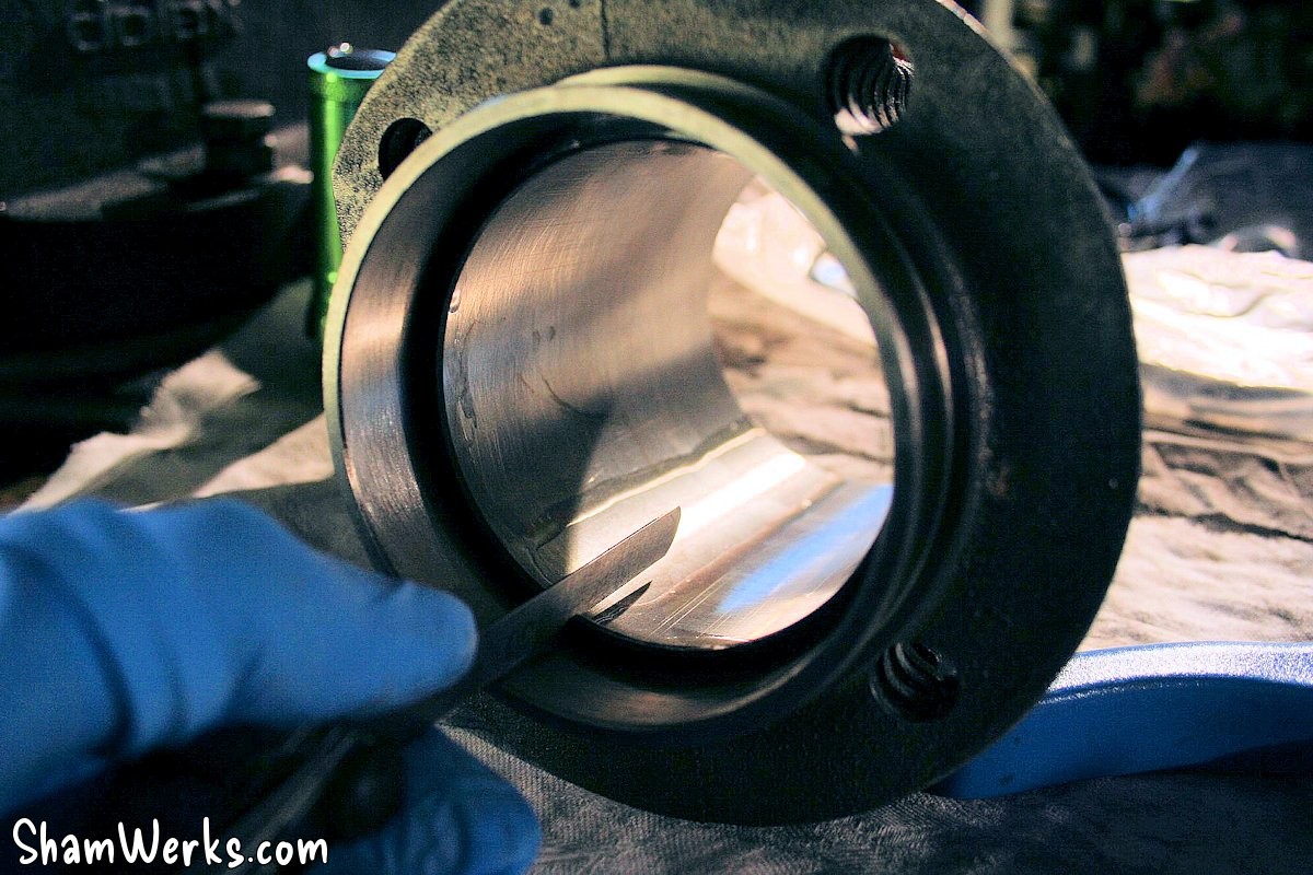
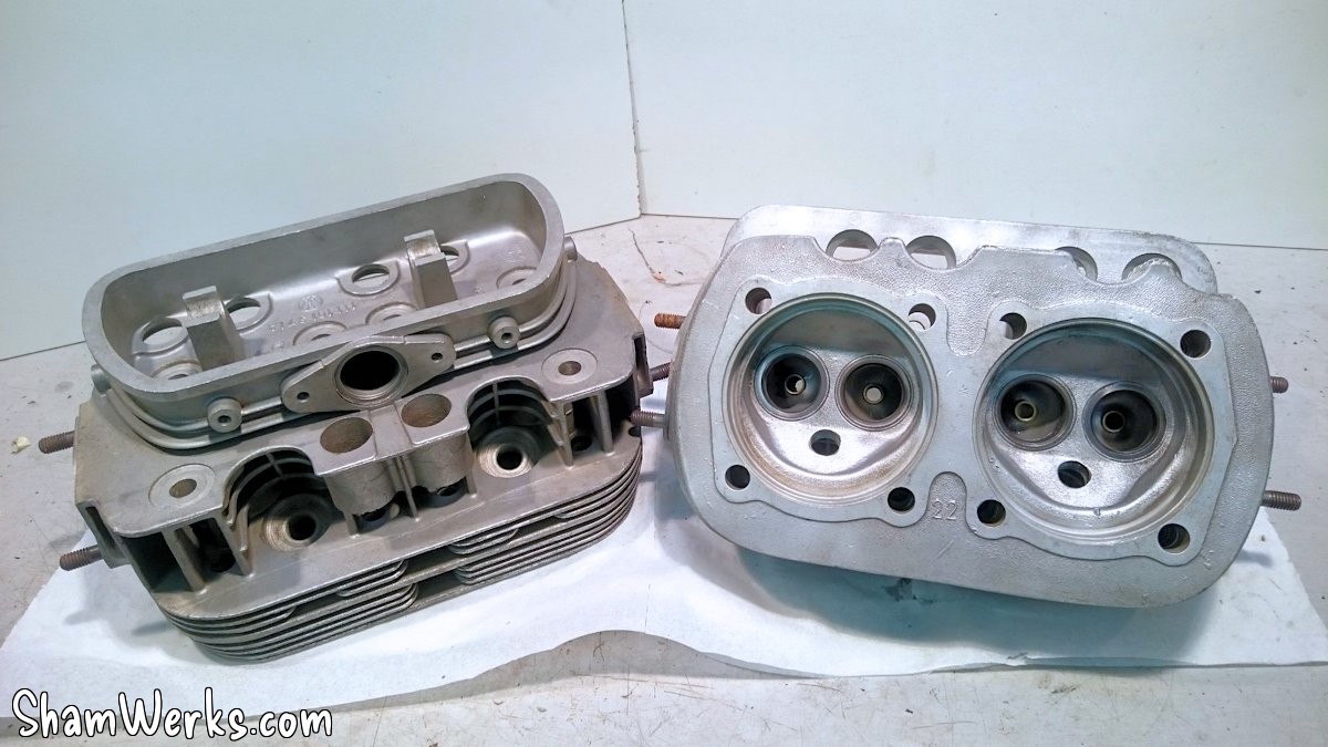
Except that now, the cylinder barrels no longer touch the bottom of the chamber, but the top on the first fin of the cylinder head; so we take out the "horned beast" (surface head) and we plane down 1.2mm, until the cylinders are firmly pressed against the bottom of the chambers (we check with a set of feeler gauges, 0.2mm of play between cylinder and cylinder head, everything is fine!).

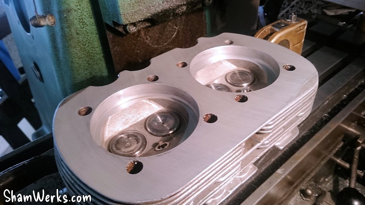
However, on the right cylinder head (cylinders 1 & 2), the fin has become really thin, like a knife blade... Not ideal, but oh well. I'll live with it.
Finally, the chambers are slightly modified with a Dremel to remove the sharp angles created by the machining (sources of heat spots and knocking), and there you have it, they are ready to be mounted!
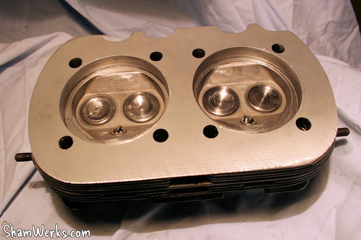
Phew... All that for this! 😉
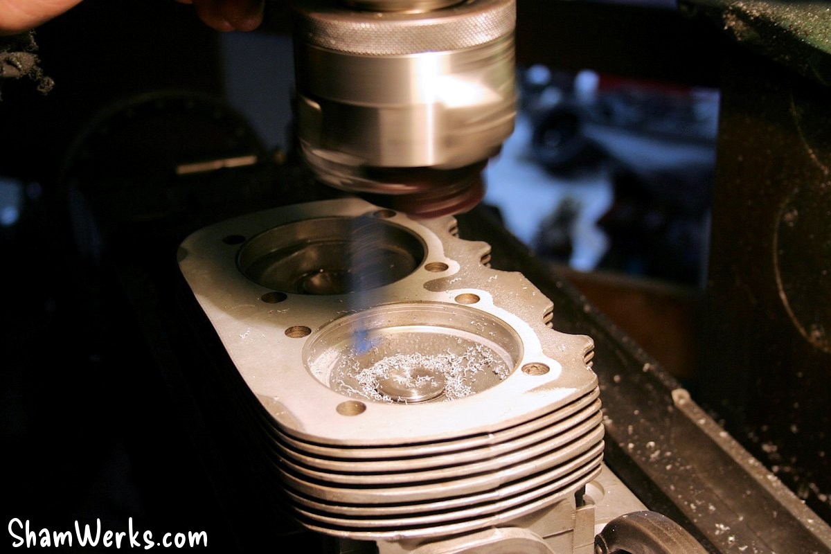
In these photos, we can see a "ripple" effect on the cylinder head after machining: the fin was starting to become a little thin and was beginning to vibrate under the milling tool.
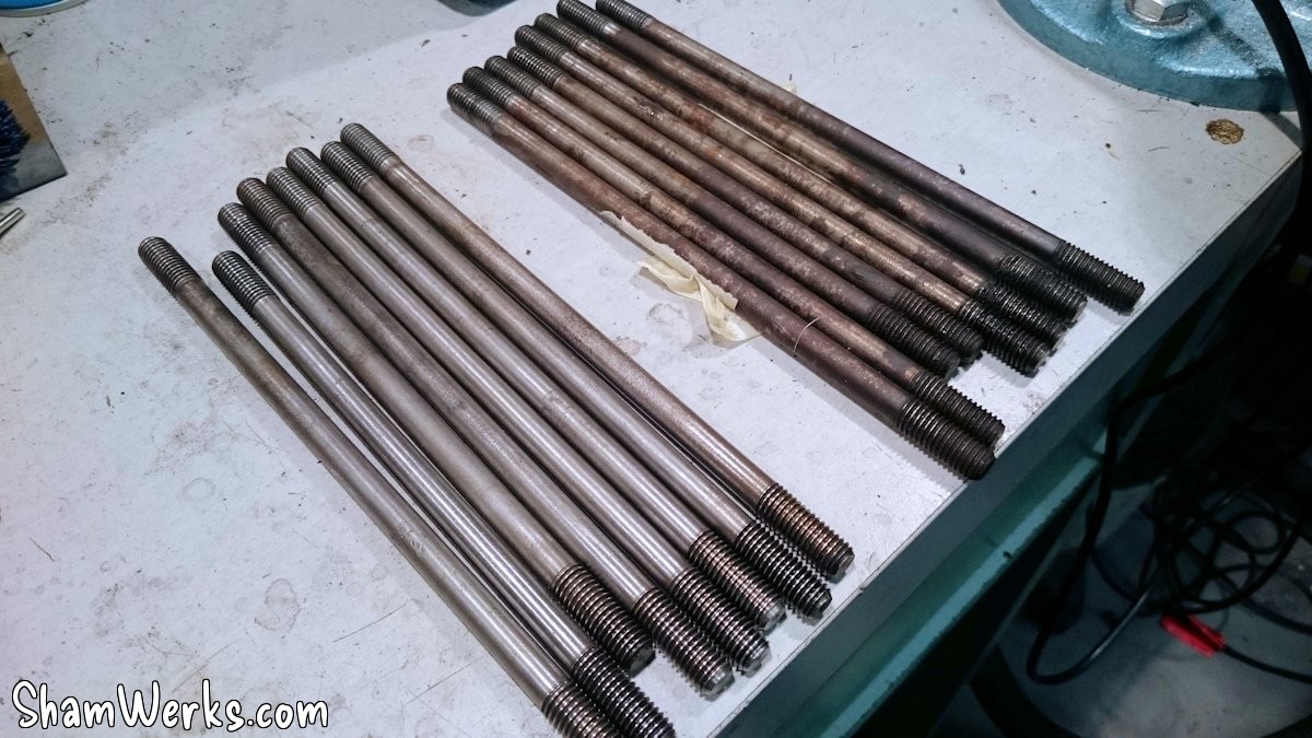
That's all well and good, but as a result, the engine is 3.2mm shorter on each side! The pushrods will therefore need to be recut to account for this reduction, otherwise the valve train geometry will be ruined... But that can wait for now, I'll come back to it later.
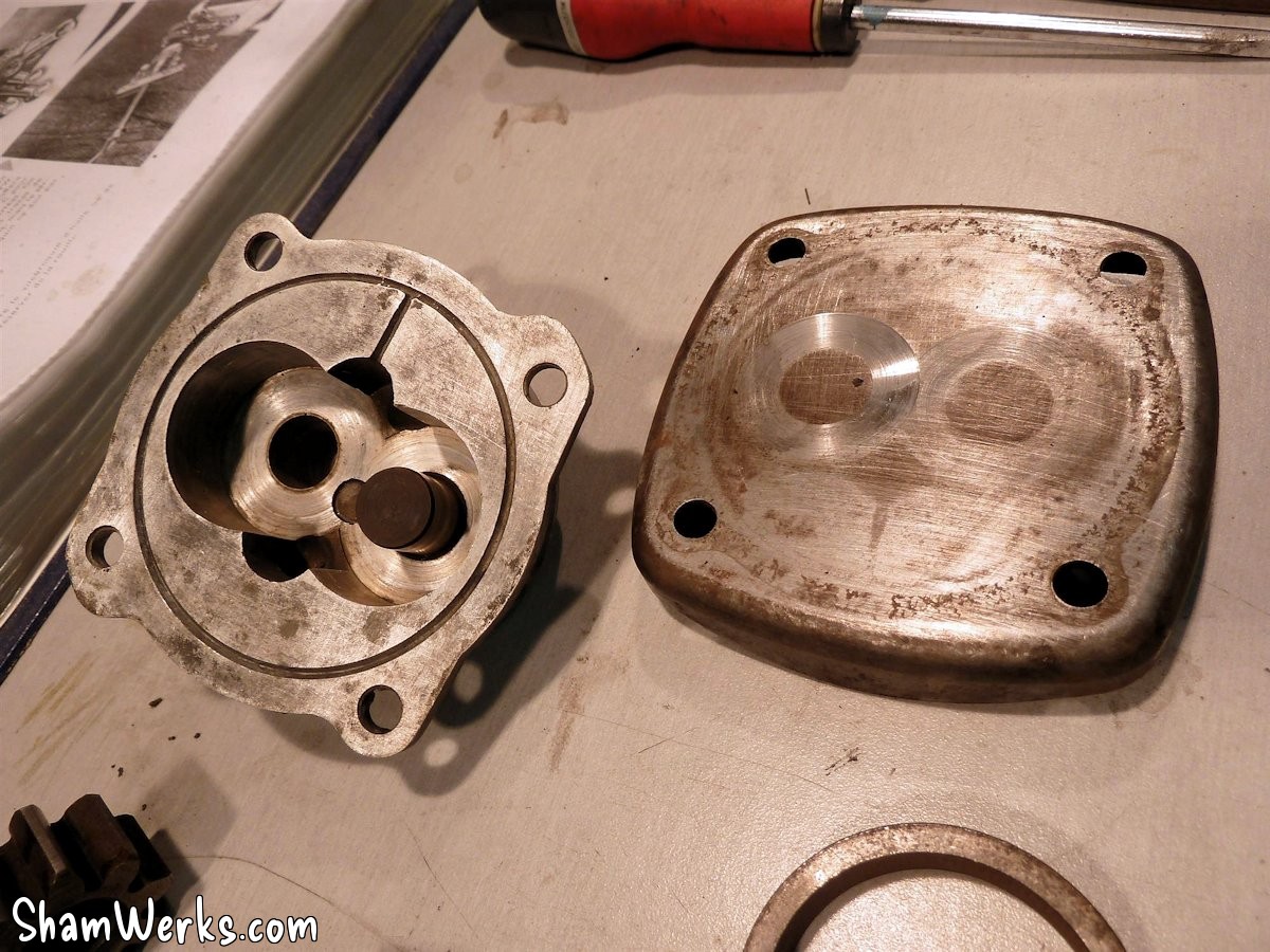
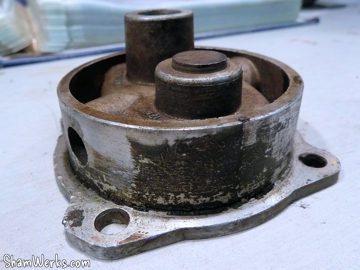
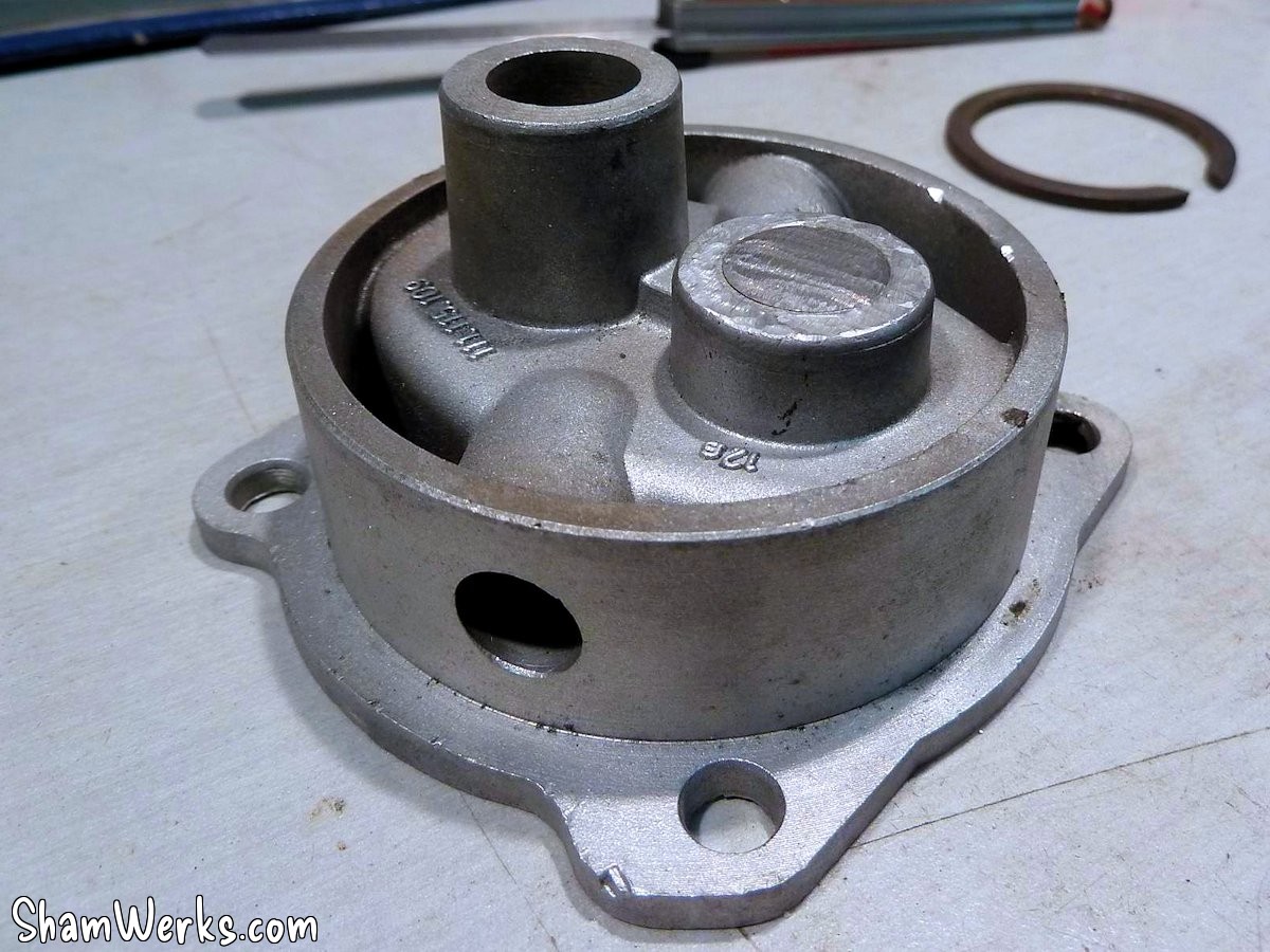
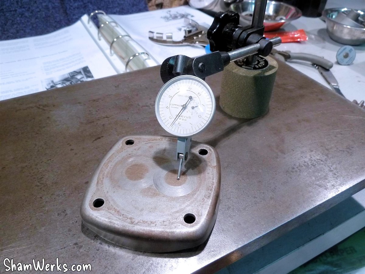
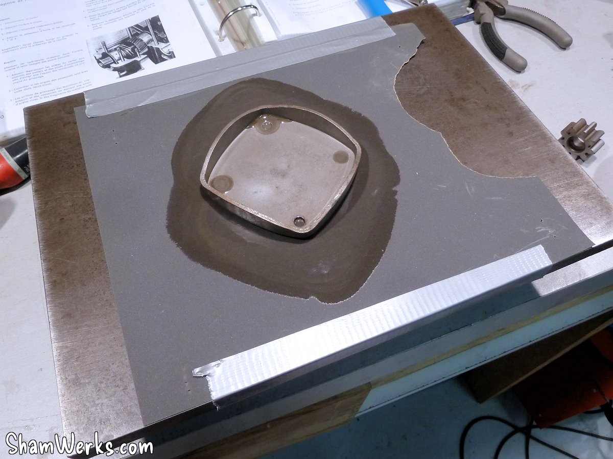
Oil pump
The oil pump cover was badly marked... I sanded it on surface plate with oil-lubricated sandpaper to remove those unsightly wear marks.
The oil pump body is bead-blasted, its tenon ground to prevent any interaction with the camshaft, and its passages aligned with those of the block. The face is also slightly flattened, just to remove traces of oxidation; it was clean.
Good for service!
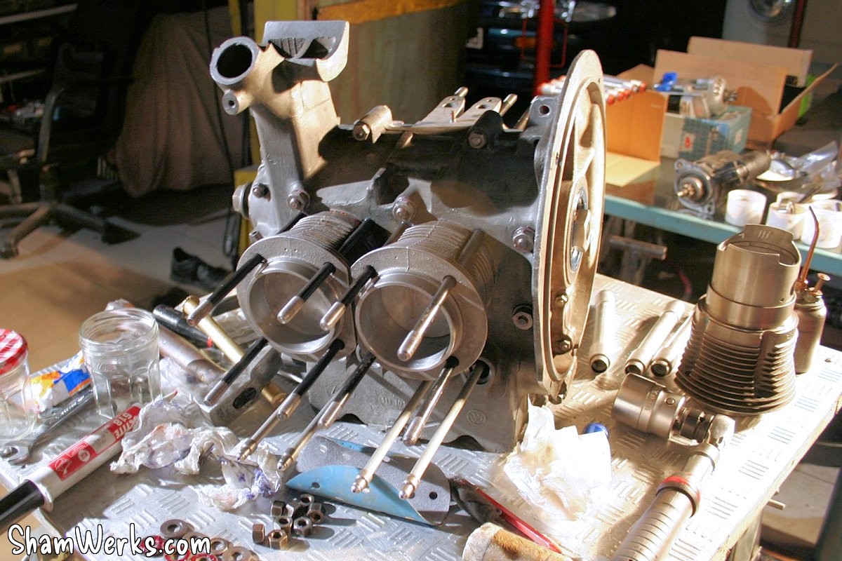
Closing the case
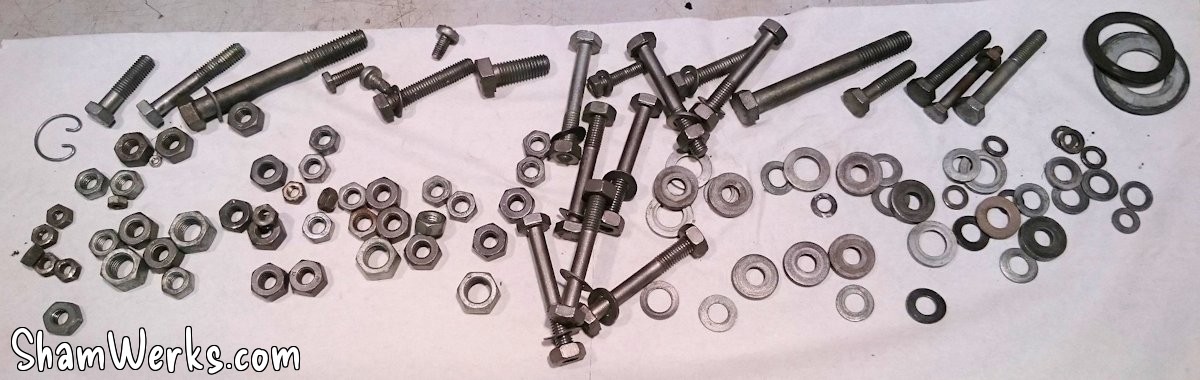
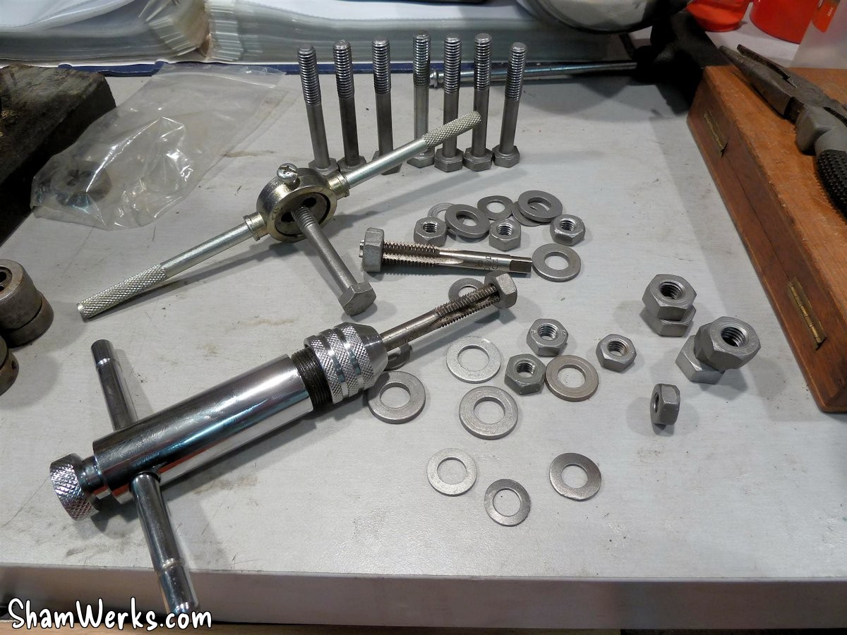
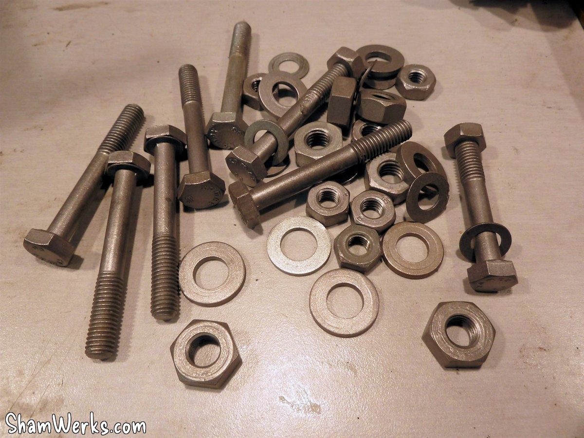
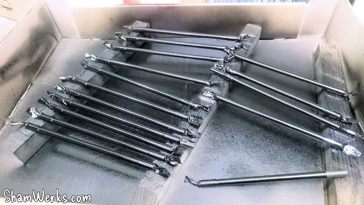
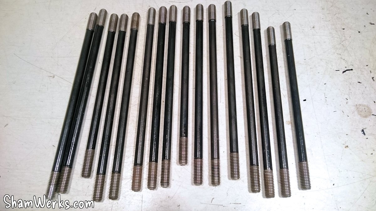
To do a clean job, I'd already bead-blasted all the screws (yeah, I'm going to make myself a "I ❤️ beadblasterz" T-shirt), and I ran all of them through a tap and die. The cylinder head studs were stripped (it's quick on the lathe), run through the die, and painted to prevent rust (#Overkill).
I didn't take many photos of the assembly; it was getting late and I had to finish up...
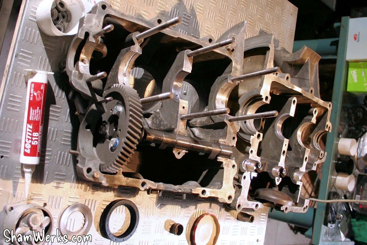
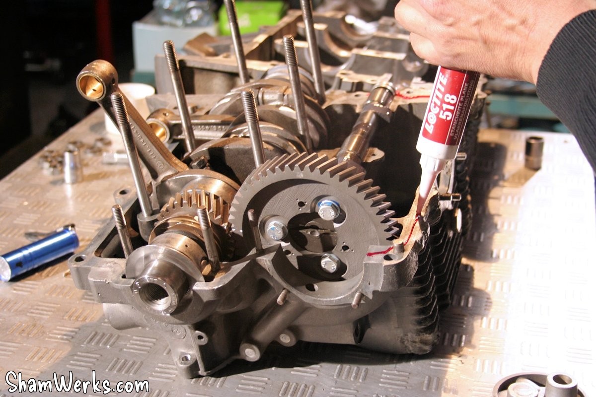
So we are preparing for the closure:
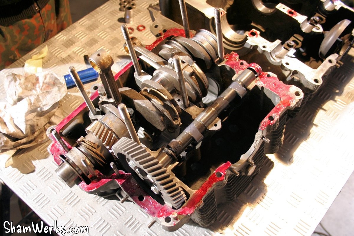
- For sealing, the gasket surface of one half of the crankcase is coated with Loctite 518 anaerobic sealant. Great product: you can take your time working (it doesn't dry out in the air), it's miscible in oil (no risk of clogging passages like with silicone sealants)... and I love its smell!
- The crankshaft bearings and camshaft bearings (no camshaft bearings on cast-iron base) are copiously lubricated with Wynn's Supercharge.
- The camshaft lobes receive a coat of ZDDP; a bit overkill considering the springs, but hey, while I'm at it...
- The bottom of the cylinders receives a small fillet of CAF; the same applies to the joints of the envelope tubes.
- The cylinder head nuts and washers located under the rocker cover also receive a coating of 518, to prevent oil leaks through the threads.
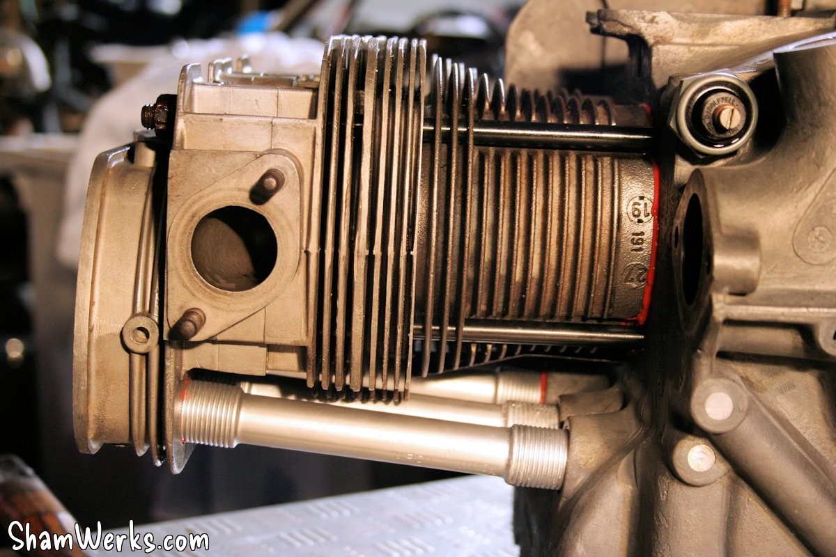
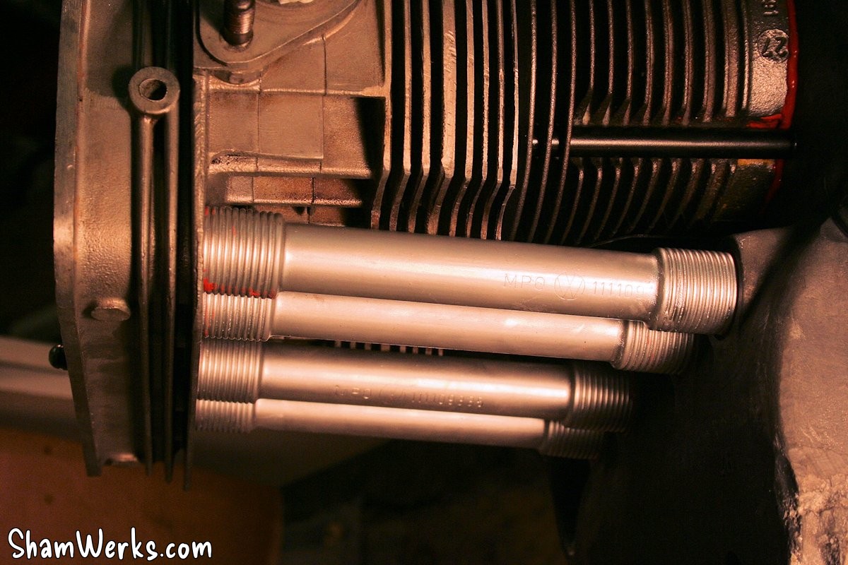
- The NOS sleeve tubes (thanks VW Classic via Slide Perf / Classic Store : €8.30 each, stings, but nice stuff) are degreased and given a thin coat of high-temperature aluminum-colored paint, so that they don't rust immediately.
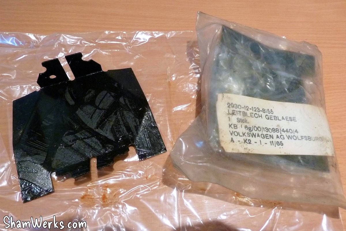
- The sheet metal under the cylinders is also NOS...
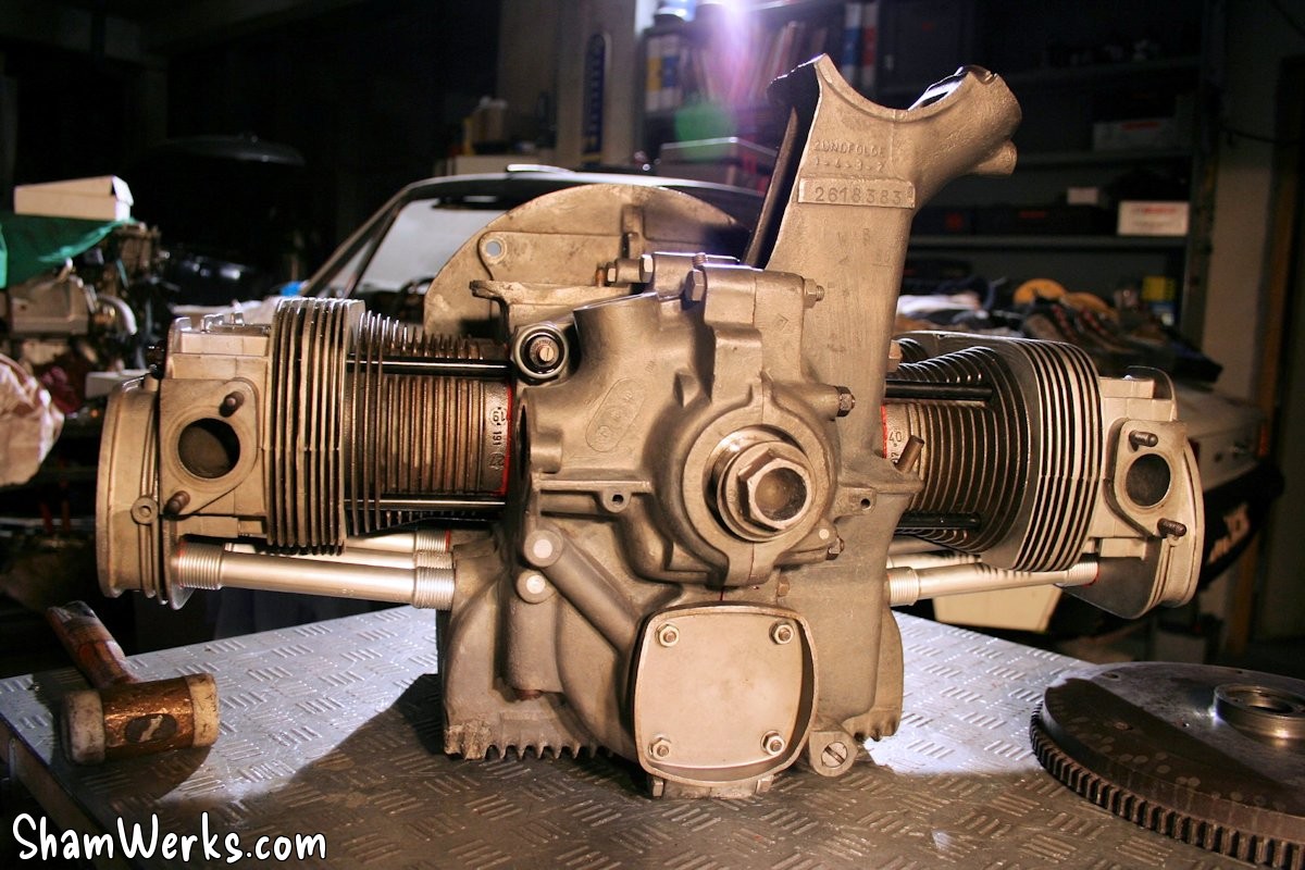
And... Ta-da! 😁
Well, we're not on the road yet, but it's a good step forward!
More to come soon!