Posted on 18/08/2017 at 07:22
Elvira : Rebuilding the 36hp, episode 9 : Flywheel and Cluch


episode 9 : Flywheel & Clutch

I finally came to the conclusion that I possibly had thrown it away by mistake (!), and right before I started looking for another one (they're not easy to come by, them 36hp flywheels), I gave a call to my friend Laurent, to ask if I had not left my flywheel at his workshop when we closed the engine block... I didn't expect much as I thought I remembered him telling me it would be better to keep all the parts together...
But he told me "yes, sure your flywheel is here!!".
GRRAAaaaaRRRGHh!!!! So much time lost! Damn, I could kick myself in the ass! #StupidOfTheYear
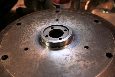
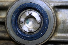
Anywayyyyy... On my flywheel, the oil seal running surface was pretty dull : some pitting, lots of oxydation... In order to avoir any oil leakage from there, I had to do something about it.
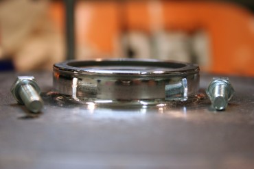
So I polished the running surface, starting with dry sandpaper 320 / 400 / 600 grit, then with oil (WD40 is your friend) 800 / 1000 / 1200 / 1500 / 2000 grit. I ultimately use 3 polishing compounds, of increasingly finer grit, applied with a felt wheel on my Dremel tool.
I take this opportunity to ever so slightly round the top angle, to make sure the oil seal won't get damaged when putting everything together.
And Tadaaaa! Shiny-shiny!
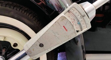
That's the opportunity for me to bring out my BIG torque wrench, the one I use to reach the 35 mKg needed to properly tighten flywheels and rear wheels' central nut.
First step, find a set of shims, cuz' as expected, the ones I have don't allow me to adjust the play correctly... And as usual, the 36hp shims aren't the same as Type 1's, and much harder to source!
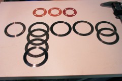
Long story short, I buy a couple of 0.32mm shims from VW Classic Parts, take out the ones in my original engine, and I end up with a pretty good assortment of shims in various thicknesses, plus 3 paper gaskets of various thicknesses.
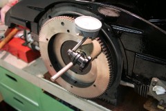
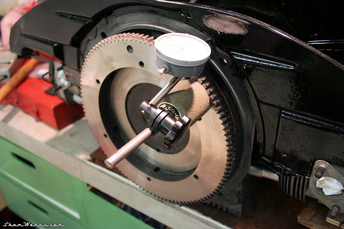
Without the paper gasket between the flywheel and the crankshaft, I get a little over 0.03mm of end play, measured with a dial indicator. After 4 assembly/torquing/disassembly sessions, I manage to find the right set of 3 shims (always install 3 of them, for relative rotation speed reasons) to get 0.10mm of end play with the paper gasket on. I would have prefered it to be a tiny bit tighter, like 0.08mm, but it will do. I give the oil seal a good dose of lubricant, put the flywheel on, and torque the central nut (with a drop of blue Loctite medium threadlocker). Just for later reference, if you ever had to look for 36hp shims : here are the VW references. Good hunting! :
- 111 105 281 : 0.24 mm
- 111 105 283 : 0.30 mm
- 111 105 285 : 0.32 mm
- 111 105 287 : 0.34 mm
- 111 105 289 : 0.36 mm
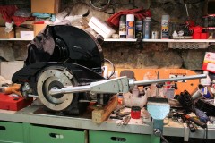
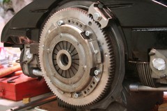
The flywheel had been re-surfaced and balanced with the crank and clutch assy (work done by Slide Perf in March 2012!! It's really high time for me to finish this engine!
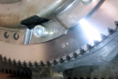
A "1" mark had been stamped to make sure the flywheel is in the same position as it was balanced ; same for the clutch assembly, with a "0" mark. At least, the bloody thing shouldn't wobble around.
The clutch assy screws are torqued (2.5 mKg) and secured with the usual drop of Loctite.
That's it for today! Yet another checkbox ticked out!
Hopefully this engine should run in no time now! (wishfull thinking...)
Posted on 09/09/2021 at 12:53
Elvira : Brakes and Pedals assembly rebuild

Elvira '59 :
Brakes and Pedals assembly rebuild
Brakes and Pedals assembly rebuild
Ok, I'll give you I've not driven that much in the meantime, but anyway, I don't feel secure driving not knowing what I got behind the middle pedal - especially with my almost 4yo son who can't wait to go for a ride! Additionally, the (much too) long immobilization of the car caused troubles, I already had the brakes locking while I was hand-pushing the car around the workshop.
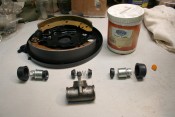
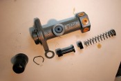
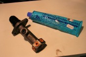
So, here we go, the full Monty, let's rebuild everything new : master cylinder, wheel cylinders, drums, flexibles, shoes, springs... And while we're at it, bearings, and seals. The wheel cylinders, just like the master cylinder, before being installed, are taken apart, cleaned with brake fluid (a toothbrush is great for that), and then slightly lubed with ATE brake grease (which is miscible with DOT brake fluid - do NOT use standard grease here!).
This important as these parts, when stocked for long periods of time, can get "sticky", and not work properly. So yes, that one additional step, but the difference in the smoothness of operation is really worth it.
Rear brakes
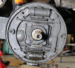
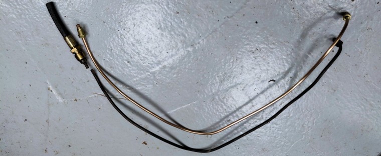
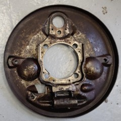
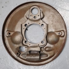
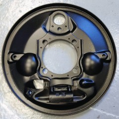
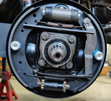
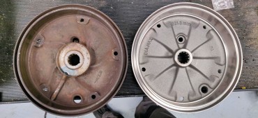
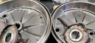
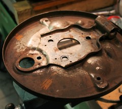
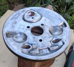
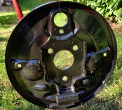
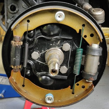
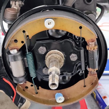
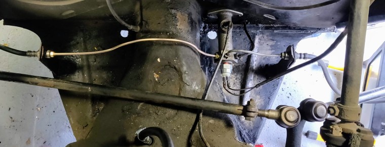
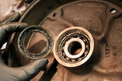
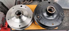
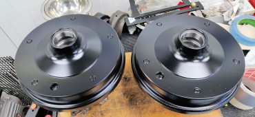
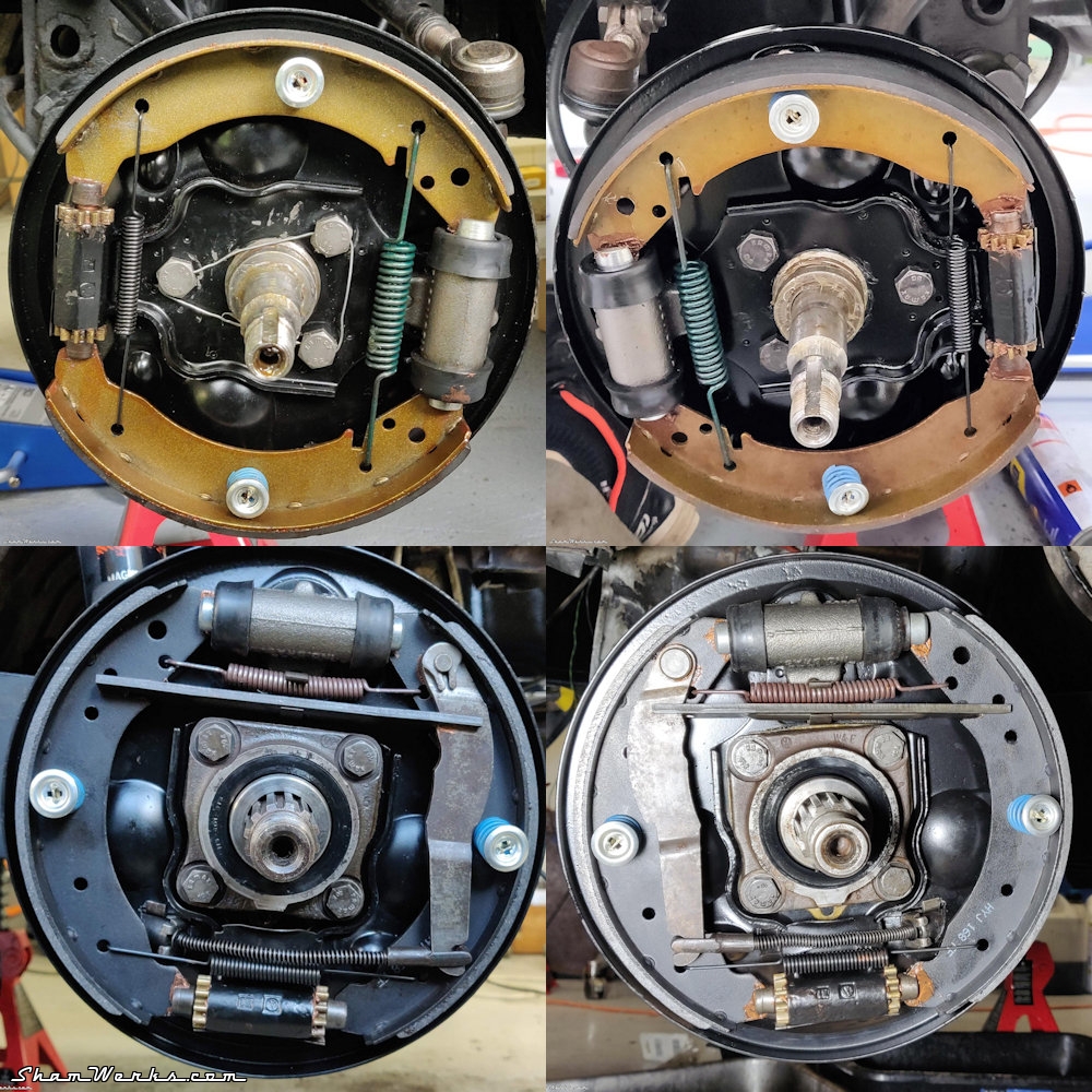
Here we go, let's disassemble everything, it looks pretty oily... T'was high time to replace the brake shoes, don't you think?One bad surprise when taking down the right side, the flexible brake line was so tight I haven't been able to disassemble it (even after trying all the tricks in the book, heat, penetrating oil, vise grip on the brake line wrench...). I finally had to cut it and remake two rigid lines from scratch. And since everything was out, I changed the rear bearings at the same time, cobbling together a tool to extract the original ones. Then it's business as usual : cleaning, blasting, and painting to reassemble anew. The brake plates are surprisingly good looking under the dirt. I use Hammerite spray paint for the first time, to give it a shot, I've never used it before. Finally, I give the new brake shoes a slight bevel with a file, degrease them with brake cleaner fluid, and put everything back together with a touch of copper grease on the friction points... The rear drums had reached the wear limit (231mm), and they were pretty heavily marked by the shoes. Those were the original drums, stamped July '59, they were due to get a replacement!
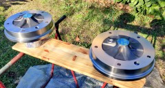
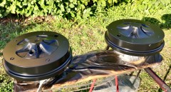
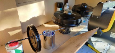
The reproduction rear drum don't feature the original oil slinger hole, so I measure 12 times (you know the drill - pun intended - c'mon, I'm a dad now, I get a pass for dad jokes), and drill a Ø8mm hole on each. A bit of grinding/filing, and the oil slingers can go back in. Now time for painting : degreasing, light sanding, re-degreasing, masking, re-re-degreasing, and three coats of Hammerite spray paint (hey, Hammerite people, I'm open to sponsoring!
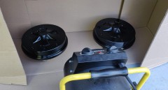
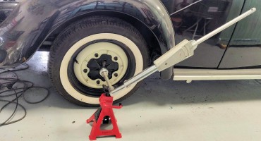
One trick when painting in winter : I'm putting all the parts in a large cardboard box, with a shop heater blowing in front of it. .. This way everything's at the right temperature for the paint to dry correctly. I actually even put parts before the first coat also, to prevent them from being too cold, possibly creating a condensation effect ; the paint spray itself goes in too, to get the paint inside more fluid before spraying. While I was at it, I replaced the suspensions bumper that had been cut down at some point by the previous owner, as he was riding much lower... But I drive at original height now! There were are, rear drums are ready to reinstall ; time to grab the big torque wrench to tighten the nuts at 30 mkg. Let's have a look in the front now!
Front brakes
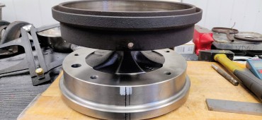
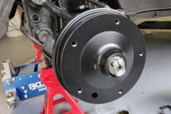
Same treatment for the front brake plates, except I had to wire-brush them instead of blasting, as being in between workshops, I did not have my air compressor and blasting cabinet at hand. And same as in the rear, I re-assemble everything anew, with a touch of copper grease on friction points. Note for self : the bigger of the two springs goes on the cylinder size... I had it wrong the first time.Behind, same thing as in the rear, I had to make a new brake line on the right hand side, the original one being way too crusty. Front drums were still within tolerance (barely), I could have kept them... But I finally decided to change them too, having everything new for my peace of mind. I'll keep the old ones if I ever need to go back...
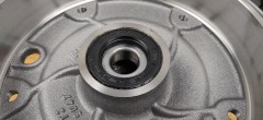
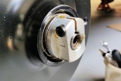
The bearings were cooked : broken cage, balls falling away, steel filling in the grease... It was time to get them replaced. Those I mount instead feature conical rollers, which looks more "mechanical" to me than the original ball bearings.
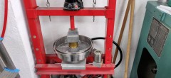
I remove and re-install the bearings with the hydraulic press I found throw away on the curb - it's always worth having a look there, one man's trash being another's treasure and all this.
Pedals assembly
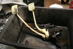
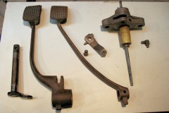
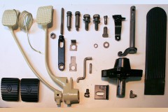
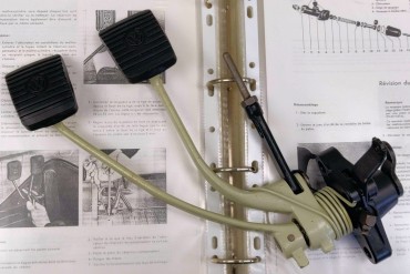
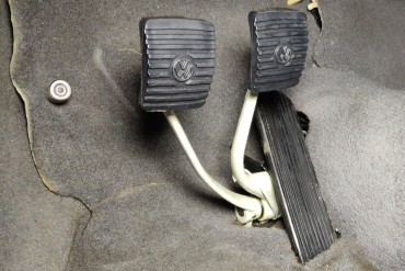
In for a penny, in for a pound (make it cent & dollar if you're a yankee) : let's rebuilt the pedals assembly while I'm at it. The previous owner of this car repainted some parts with this ugly "vanilla-yellowish" color that I cannot stand anymore. So I repaint the whole pedal assembly, in L87 PearlWeiss, just like the wheels. Paint stripper, blasting, primer, 3 coats of paint : much better.I'm using a rattle spray can L87 from Sprido, priced at 18.50€. Result looks clean, I'll probably use the same on the steering wheel when I get there. To finally get rid of that God forsaken yellowish sh*t, I'll still have to repaint the seats frames, steering column, steering wheel, the bar below the rear seat, and the electrical circuit cover in the front trunk. But this will have to wait until another episode.
This yellowish horror had already been repainted on the hand brake lever, gear selector and wheels, back when I had given the whole exterior a lick of paint... in 1998!
But nothing being simple ever, the clutch cable wasn't the right model, too short, and the throttle one was kinda sticky... Anyway, after I took everything out, replaced the clutch cable, it finally works perfectly. Pumped some grease in the pedal assembly, and the feeling/touch of the pedals is completely different, much smoother. We'll see when driving!
OK, let's bleed the whole thing and we'll have enough to stop in security, enough for today... Safe trip everyone!
Posted on 22/09/2021 at 21:30
Elvira : Rebuilding the 36hp, episode 10 : Heater Boxes


episode 10 : heater boxes
Heater boxes
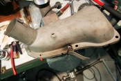
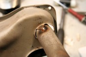
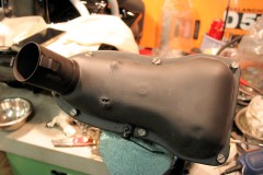
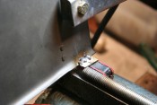
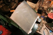
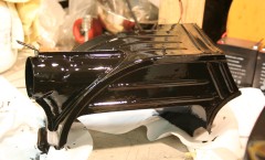
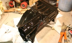
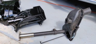
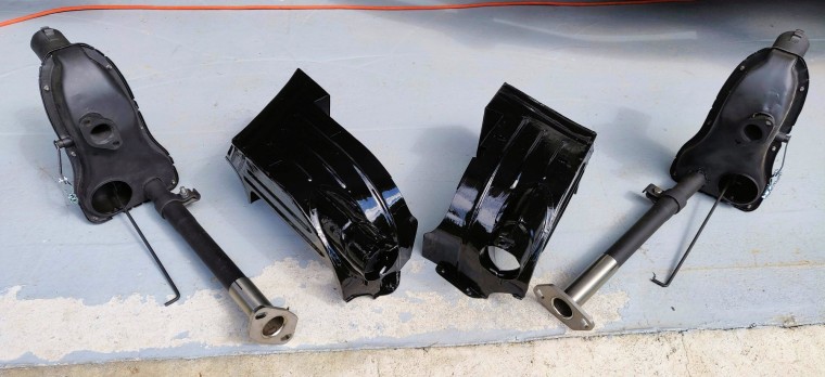
I initially only had J-Tubes on my engine ; so I started by sourcing a pair of used heater boxes. A bit of rust, a couple of dents and holes, a locked mechanism and a missing lever... But nothing patience, WD40 and a MIG can't fix.One of the mechanisms is seized by rust (articulated lever) ; WD40 doesn't help, and the bearing finally ripped off as I was trying to free the lever. I finally managed to persuade it to move after clamping it in the vise, so I plug-welded it back on. Done.
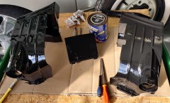
On the other side, the mechanism was not seized, but was missing the lever actionnating it. Using a piece of masking tape, I copy the shape of the one present on the other box. Two saw cuts, some filing and drilling two holes, I have a pretty good copy ready to plug weld in place. All parts finally get a couple of coats of rattle-can Rustoleum hi-temp paint (supposed to handle up to 650°C/1200°F, but I won't hold my breath). All the hardware gets bead blasted, and it's ready for reassembly.
Engine tins
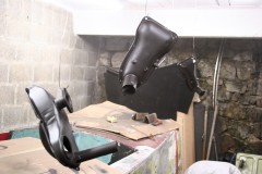
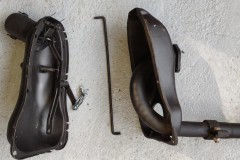
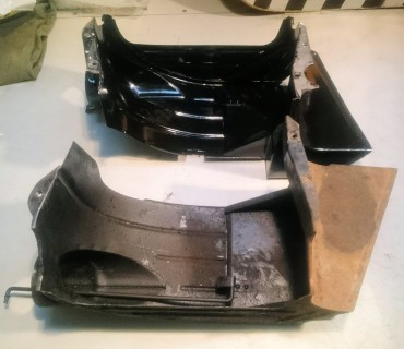
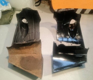
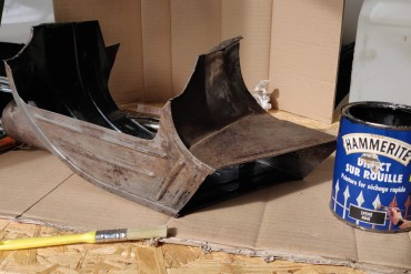
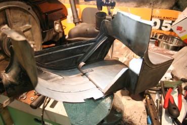
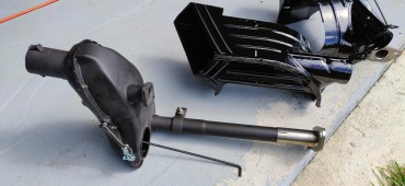
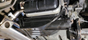
For the whole system to work properly, and for the heated air to be actually forced into the passenger compartment, it requires the under engine tins to be present with their moving flap to redirect the airflow. I did not have those tins on my original engine, and they are getting harder to find (and never built as reproductions). But with some patience, regularly checking online ads, and some bucks, I finally found a pair.The ones I got were in an ok state, with just a little tab broken on one of the moving flaps. Thorough clean up with naphtha and brake cleaning fluid, then bead blasting to get rid of the flaking paint. And since those are below engine tins,exposed to road gravels, I brush two coats of Hammerite, as it will protect them better than any body paint. Here you can see the left on in its original state, and the right one after full treatment : I can then focus on fixing the broken tab on the other heater box : only took some MIG persuasion to tackle it. Bead blasting again it is, and a lick of paint again : And... Taaadaaaaa!!
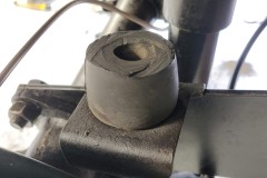
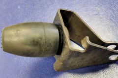
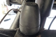
While I was at it, I also changed the flaps control cable, the little rubber boots back where the cable gets out of the chassis, and the fittings on the boxes levers ; next I'll put all this back in the car, and make sure the flaps actually move as expected!
But this will have to wait until the next episode!
Posted on 21/11/2022 at 23:19
Elvira : Rebuilding the 36hp, episode 11 : engine installation


episode 11 : engine installation
Engine Bay
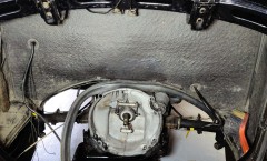
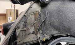
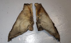
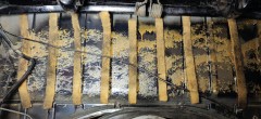
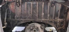
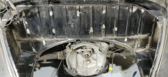
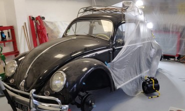
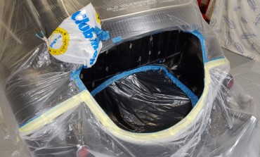
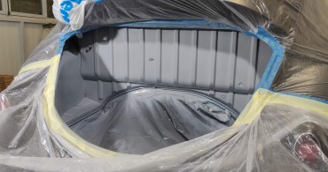
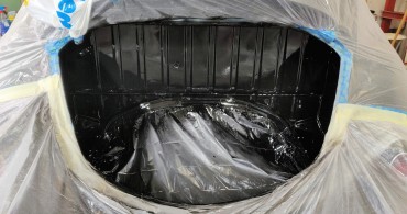
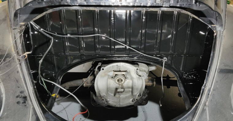
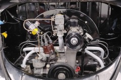
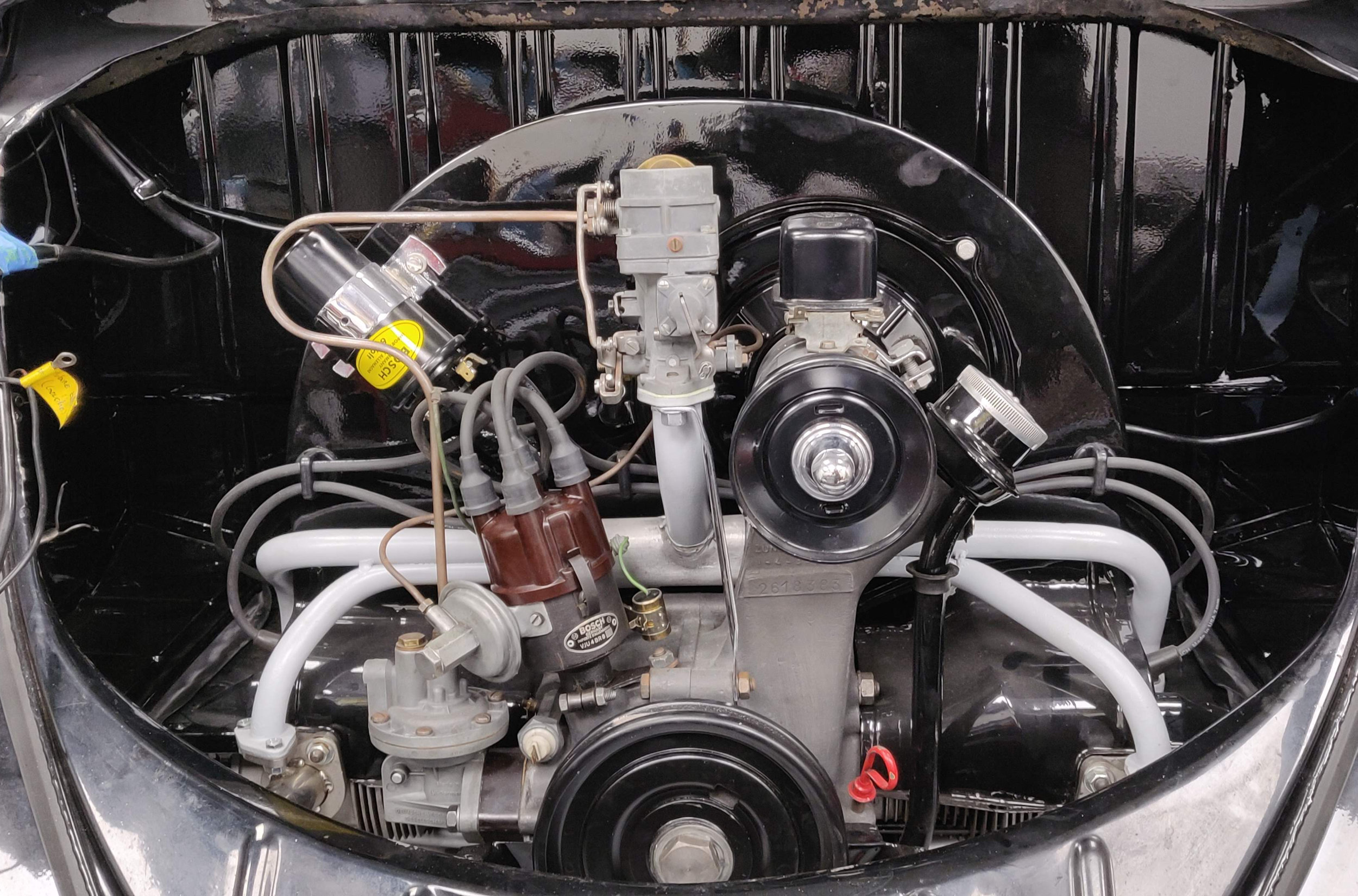
As it was inconceivable to put back my beautiful engine in a dirty engine bay, I decided to get rid of the original sound deadening cardboard, as it was pretty banged up - and I much prefer that look, even if it means a louder engine. I also get rid of the little cushions hidden in each side of the body top, as they tend to promote rust. Then I'm in for a long session of acetone cleaning to remove all traces of glue (they had kind of a heavy hand with glue at VW back then). I then grind off the pointy tabs that used the original cardboard... I masked everything, protected the workshop around... Which won't be enough in the end, I had underestimated the overspray, the workshop floor will keep some marks... Then primering, light sanding, and finally painting the engine bay using 2-components polyurethan spray from VerniciSpray - this is not a sponsored message, I quite like their products and service (already used on the engine tins). The result is pretty neat actually, don't you think? (brand spanking new engine seals too, while I was at it)Pre-install preparation
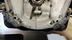
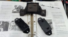
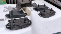
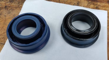
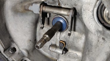
Since the engine was out, I took the opportunity to replace the gearbox stands, including the nose one, a specific model for year 1960 (VW reference 111301265C). I also replaced the gearbox drive shaft seal, split-case specific model (VW reference 111307113C) : it has a sort of lip around it as its housing does not feature any shoulder to hold it. I still have the original 1959 seal in place, which was hard as hell and screaming for a replacement...Gotta be cautious when installing it, as because of the lack of shoulder to stop the seal, it's rather easy to tap it a bit too much and have it go too far into the gear case. It's then pretty difficult to get it out without damaging it - don't ask me how I know that.
The clutch lever spring on the gearbox was broken (no idea why/how, it broke on its own), so I replaced it too. Warning, it's specific to split cases too, VW reference 111141723A.
I've replaced all the fuel lines, the fuel filter (installed under the tank), and the fuel tap under the tank that always leaked a bit since I had this car. I'm a bit paranoid about fire, I'll probably install a Blazecut too in the near future...
I replaced the spark cables with new Bosch ones, while installing the little rubber cable supports specific to 59-61 models (VW reference 113905451), with a dab of vaseline so they mount easier on the fan shroud. I keep the original distributor, I'll replace it at some point with a 010...
Engine reinstall
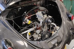
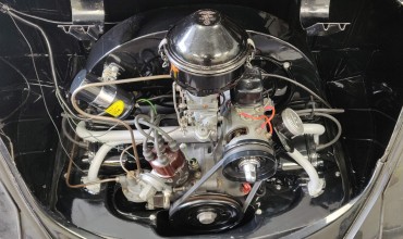
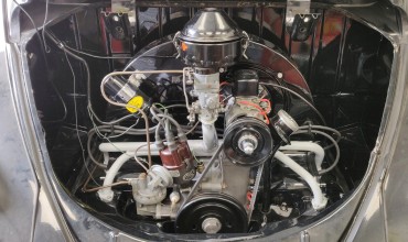
Well... I guess time has come now, the engine is now ready to go back in its bay. Which I manage to do alone in 15mn, one of the advantages of small stock engines...So for once that was pretty easy, at least something not fighting me!
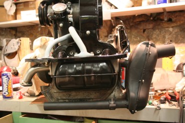
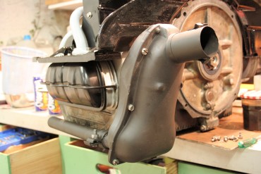
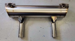
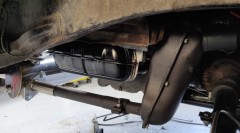
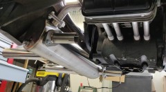
With a bit of adjustment on the engine tins I fit them under with the heater boxes (see their restoration on my previous post), and finally connect everything to the exhaust.
First start
Finally, April 13th 2021 (yeah, yeah, I know, I'm Hell behind my articles publication schedule!), everything is ready for a first crank... I wasn't feeling so sure I gotta admit.Setting the ignitor at 7.5° static advance, adjusting the rockers, priming the fuel line and pump with a vacuum pump (one of those used to purge brakes, works great for fuel too)... I also primed the oil circuit by unplugging the ignition coil and cranking the starter until the oil pressure light blinked out (takes 20/30 seconds on a brand new engine). This will prevent the crankshaft from running dry on its bearings...
And then, well... A squirt of Start Pilot, deep breath, and... Phew, that was one serious step crossed here! Gotta do some small crab adjustment, shoot my stroboscopic lamp to check ignition, plus a couple of small things here and there, and back on the road!
OK, my very first drive out ended up on a tow truck because of a failed fuel pump lever, see my edit from 2021/10/22 on the dedicated post... But since then it drives great!


