Kitty Injection : 1776 part. 3 : Short Block
Here's a long-awaited article, as I started writing it over 10 years ago! 😉 Maybe go get yourself before you keep reading buddy, this is gonna be a long one.
Actually, the last episode of this series dates from June 2014 ... Yeah, I'm not exactly an example of speed, right? 😁😁
As a consequence, those of you with a keen eye will note that some photos were taken in my old workshop , and others in the new one...
Come on, let's not lose hope and continue with the closure of the "Short Block".. It's high time we put all these parts together to make an engine:

I won't lie, I'm getting a little impatient for this engine to run... 😁
Metrology & methodology
I get everything I can through metrology on this build, so as to avoid any unpleasant surprises - and to satisfy my OCD. 😁
So I'm taking out all my metrology tools collected over the years: micrometers and their calibers, bore comparator, adjustable gauges (not in the photo), calipers, thickness gauges, etc... Well, I know that I'm not doing this in a clean room under controlled temperature, nor with regularly calibrated tools, but within a few hundredths I should be pretty good.

Obviously this requires a bit of organization; to be able to find my measurements easily, and compare them to the VW tolerances, I note everything down in an Excel table (well, actually a Google Sheet). This allows me to access it from anywhere, note the values in the workshop when I measure them, and check the tolerances at a glance.
You can see the result below, or by following this link to have it in full screen: metrology 1776 KG.
I was freely inspired by the Engine Blueprint Specifications Worksheet available on TheSamba to create my file, which I can easily use for my next engine...
At the time of writing these lines the compression ratio is not correct since I haven't taken care of the cylinder heads yet, but I will update the sheet when I do.
Crankshaft
This is a part that I had to chase for almost 7 months because of a not very well-organized parts dealer... In short, fortunately I have a father-in-law in the US to ensure stewardship on this one! Thank you Yves!
So, it's a Scat Volksracer 69mm counterweight crankshaft, "Straight shot" oil galleries and not "cross-drilled", forged in nitrided 4340 chromoly... Beautiful beast.


Although the crankshaft is sold as supposedly already balanced, I still got it balanced myself (at Feller's), with its flywheel and clutch mechanism; the damper pulley had already been balanced on its own. At least I would have a complete line that runs smoothly! (thank you Loïc for lending your crank shipping crate)
The alterations made to the crank by the balancer are not negligible, for a supposedly balanced part... Food for thoughts.


It may be a beautiful piece of engineering, but it still goes through metrology, after a thorough cleaning (acetone to remove storage wax, brake cleaner, and cleaning brush for rifles in the galleries). Result in the spreadsheet above, everything is on point. Next!
Bearings
Each bearing (VW NOS original) is identified with a marked, and its oil groove aligned with its oil supply gallery; in some cases the gallery was half blocked! A touch of paint around the edge of the oil inlet, transfer to the bearing, machining with a pneumatic milling machine, finishing with sandpaper... And that's it.


Okay, now it's a matter of measuring the clearance between the crankshaft and the bearing... In the end, that's what matters, and there are several ways to go about it.
VW recommends a clearance of 0.04mm to 0.10mm on bearings 1 and 3 (wear limit of 0.18mm), and of 0.03mm to 0.09mm on bearing 2 (wear limit of 0.17mm) - a little tighter therefore, normal, it is the central bearing, the one which absorbs the most efforts.
They also recommend 0.05mm to 0.10mm (wear limit of 0.19mm) on bearing 4 (the one which is smaller, on the pulley side), but I am not equipped to measure it; not a problem, it is less vital than the other 3.
Okay, let's move on, we're going to measure these clearances...
First method : find the difference between the inside diameter of the bearing and the diameter of the crankshaft journal. See measurements in the spreadsheet above.
This method works fine I guess, but requires to be very accurate, as measurement errors add up. And when we're talking about hundredths of a millimeter, the temperature of the tool itself can influence - and you can imagine that my garage is not thermoregulated, eh... 😁
Second method : we take the minimum diameter on the crank bearing; we block the micrometer on this value, whatever it is, we will not even read it. We will then calibrate the bore comparator to zero using the blocked micrometer: we can then directly measure the bore/bearing clearance with the comparator.
This is my favorite method, the most accurate in my opinion.


Third method : Plastigage.
For those who don't know, it is a sort of soft plastic filament, which you clamp between the crank and the bearing. Then you tighten the case to torque, the filament gets crushed, and you then measure its width using a small scale supplied with the product, to figure out the clearance between the parts.
It’s a vintage method (the product has existed since 1948); not the most accurate in my eyes, and usable only on bearing #2 (bearing in two parts)... But it requires little material and it is easy to implement.


I went through all three methods of measurements and got consistent results, within VW tolerances.
Validated!
Flywheel
On the flywheel side, I keep the one I had original, which I got machined to get it lighter and drilled for 8 dowel pins (reamer finish):


The clutch mechanism is a Kennedy Stage 1; it got a mark after balancing (in yellow) to put it back in the right place at assembly time:


Camshaft & Lifters
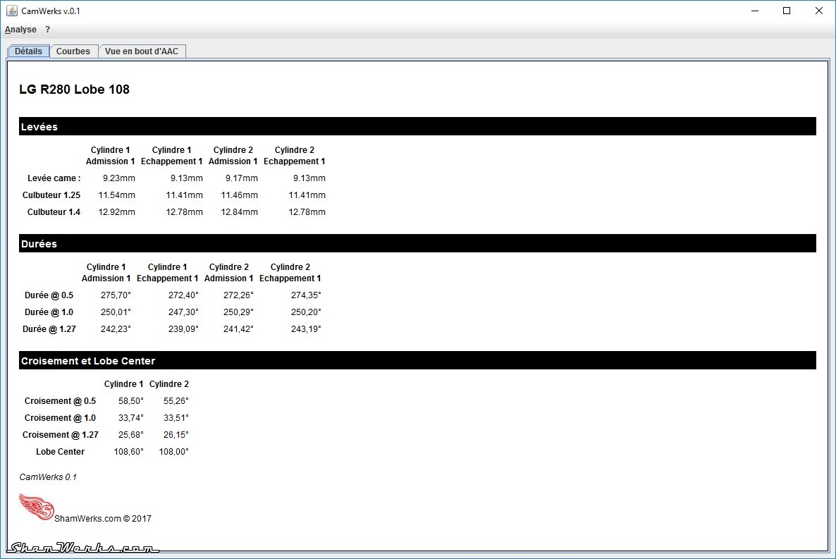
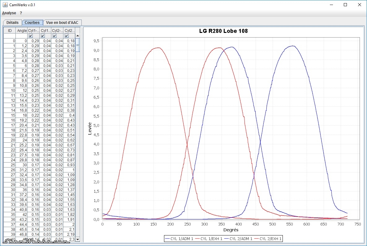
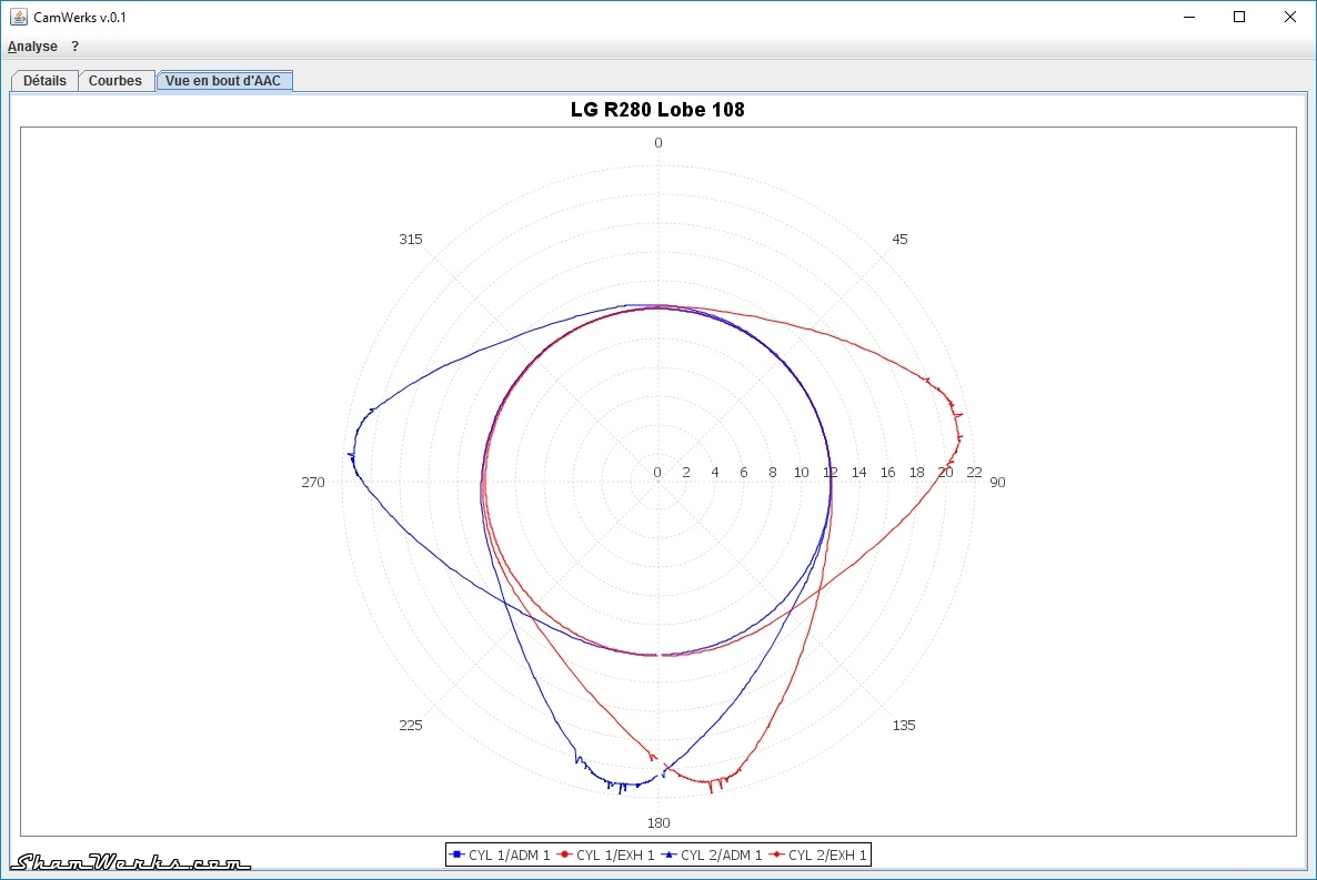
The camshaft is an L&G R280 Lobe 108°. To check its characteristics I built a camshaft measuring bench , I'll let you follow this link to check the details.
I use double-shouldered bearings, to have 360° guidance of the camshaft, not just the original factory 180°; however, it is necessary to check the axial play of the camshaft.
On the first assembly, I have zero play, the camshaft is in a sliding fit... No bueno.
Before removing any material from the bearing, I follow the Jake Raby method (see here / thank you Vince for the info): crankcase closed and torqued tight, I tap with a mallet and a brass cylinder on each side of the camshaft to seat the half-bearings #3 (pulley side). I then measure the axial play and...
Disappointment, the play is still at zero. I did follow the method, I hit firmly, but that was not enough...
So we take out the surface plate, 400 grit sandpaper with oil, and we are going to slightly sand down the bearing faces to get the required 0.1mm . To make the operation easier, I made a small tool to align the bearings halves: an old dead camshaft, grinded down to keep only the part on the pulley side.
This allows you to properly align the two half-bearings, and to sand them simultaneously, in a very uniform manner. A bit on one side, we turn the half-bearings, a bit on the other, making figures 8 on the sandpaper... Thanks Laurent for the advice, it works great! 😉
Going slowly so as not to remove too much material, I remove little by little what is necessary... After the 3rd assembly/disassembly, I have just 0.1mm of axial play, that's all Good! I finish with 600 and 1000 grit sandpaper (with oil) for a smooth surface finish.


Then, a small modification of bearing #1 (flywheel side): originally it partially obstructed the oil return gallery... A cut-off disc on Dremel and 10 seconds later, and the problem is solved (after removing any burrs with a file and fine sandpaper).
Finally, the holes on these #1 half-bearings are not chamfered: a light stroke with a countersink, held at fingertips, solves this. Not that it's mandatory as a modification, but hey, in for a penny... And remember that chamfering is what separates man from beast (I'll pay my round of beers to the one who has the reference).


There you go, after a quick deglazing with a used Jex pad, the bearings are ready.
Connecting rods
These are original VW connecting rods (311B) that I had microblasted, checked and re-sleeved at Feller's.
I then balance their weight, all within a tenth of a gram interval. To remove the bulk of the material I use a paddle disc on an angle grinder (it seems clumsy, but it allows you to work quickly and leave a good surface finish), and I refine with an electric file.


Going through with metrology obviously to check everything... Validated.
Nuts and Bolts
All original bolts (screws, nuts, studs)were cleaned with WD40, then microblasted and reworked with taps/dies (M12x1.5 and M8x1.25).
Everything then goes to cold bluing (Brunifast), mainly for aesthetics (and a little protection against corrosion): careful degreasing (brake degreaser, acetone), 3 minutes in the Brunifast bath (at 20°C min), rinsing with water, drying, and finally a bath in engine oil for at least an hour to set everything.
I had already explained the method in my article on restarting the 181 , I will not detail it further.


For their part, the cylinder head studs are cleaned on the lathe, being careful not to leave a finger there, it's not necessarily a very safe approach!
First cleaning with a scouring sponge and WD40, then a quick sanding with 600 grit, a rotary brush on a drill to clean the bottom of the threads... And finally passing the threads through the die, to ensure a correct reading with the torque wrench when tightening the cylinder heads to torque!


I know, it's a few hours of work here just for hardware... But it's cleaner and it's such a pleasure to assemble afterwards!
Closing the case
FINALLY! 😁😁😁
A quick review of the products/compounds used during assembly:
- Loctite 518: for crankcase assembly planes - the smell is super addictive. 😉
- Loctite 577: thread sealant.
- Loctite 273: normal blue thread lock.
- RTV silicone: under the washers of the 6 M12 studs
- Wynn's Super Charge: used as assembly oil, it is very thick, it sticks well to the bearings, limits friction a little during the first assemblies, and will later mix with the engine oil.
- ZDDP grease: for the camshaft and lifters, to limit wear in the first minutes of engine life.
- WD40: with a piece of used Jex pad, to clean the crankcase joint surfaces, and deglaze the bearings.
- Acetone and Brake Cleaner: to clean parts before assembly.


I start by dressing up the crankshaft, with the camshaft gear, the spacer, the distributor gear... Heating the gears with a heat gun and it goes on rather easily. On the other hand, I had to file down the spacer to remove 0.5mm, otherwise the clip would not fit... Manufacturing defect of the Scat crank? No impact anyway, I continue.


I continue with the connecting rods, making sure to mount them in the right direction (the "grain of rice" at the top, or the notches on the bearings at the bottom, same difference). The crankpin got spread with Wynn's, the bearings deglazed with worn Jex pads, then tightened to torque (3.3mkg), with a drop of thread lock, and go.


I then move on to the crankcase: making sure not to forget the pins under the bearings, nor the O-rings on the 6 M12 studs. Lifters in place (lubricated with assembly oil), with the outer retaining springs on the right crankcase for handling. I use an aluminum block which I tap with a mallet to properly position the half-bearings (central crankshaft and camshaft).


I of course re-plugged the 10 oil gallery plugs that I had opened (see this post ), as well as the oil pump outlet (because Full Flow), with the right aluminum plug and its drop of 577 - as gentlemen do.
Two steps back...
Of course, true to my principle of “ it’s never simple ”, in reality it didn’t happen that simply. 😉
As I don't have a lot of free time between work and family, I try to optimize... And obviously, when we go fast, we take shortcuts and... we miss things. 😁
Here, for example, I was convinced that my stock-stroke crankshaft turned without any interference in the case, I had turned it by hand in the half case, and it didn't seem to hit anywhere. So I skipped the trial assembly with torque tightening, and I "permanently" closed the case...
But of course, once closed, there was a counterweight that was rubbing! 😔
Long story short, that was a day and a half wasted reopening the crankcase, taking everything out, grinding/sanding the edges in the block, cleaning 518 compound around the crankcase, cleaning the dried thread locker on the bolts (each thread, one by one, with a curved tip ), removing the silicone under the washers, re-cleaning the crankcase halves carefully to remove any magnesium dust, etc... Just to get back to the same step.
I'll summarize it for you in 3 photos and we'll get back to it 😁😁:


In France we have a saying : "when you ain't got a brain, you gotta have legs". 😁
Closing the case strikes back
Take two of the closure of the block... This time it's the right one, eh? 😉
So I install (again) the lifters, crankshaft, camshaft, and oil pump. The bearings and camshaft receive their dose of ZDDP grease, and the periphery of the crankcase a thin layer of Loctite 518 (red in the photos).
Let's not forget the plug behind the camshaft, and check that the marks on the camshaft gear align with those on the crankshaft's...


Taking a big breath, after checking 15 more times that I haven't forgotten anything, and finally I close the case.... again. 😁
Loctite thread lock on all threads, a touch of RTV silicone under the washers of the 6 large M12 nuts, which are torqued in the prescribed order (in stages, starting at 1mkg, and increased to 3.5mkg in steps of 0.5 mkg). The nuts all around the block are tightened in a star pattern, also in stages, up to 2.5mkg - (15mm nuts with cylinder head washers thanks to the Berg conversion).
And finally... Tada!!! 😁


I've already fitted the alternator stand and cylinder heads studs, but for now we'll leave it there.
That's it for now, see you around soon (I promise) for the Long Block! 😉
Published on 30/06/2024 / 2 commentaires