Camwerks : DIY Camshaft measuring bench
Those of you who follow ShamWerks on Facebook already got a peek of this thing back in January 2015! Well, it was high time I finally write an article about it, right?
I stumbled upon a picture of a camshaft control bench on Vince/Panelvan's blog (here)...
As I had just bought the high-performance camshaft for my Ghia, the idea of being able to check its actual features (and verify what's given by the part's constructor) made its way ; I was pretty sure I could find a way to make it happen on a budget. And, let's put it mildly, I'm kinda stubborn. 😁
Thinking about it, there must be a way to put together a stepper motor, a digital caliper (cheap chinese models have a serial output), and an Arduino to control all of the above and push measures to a PC through USB... Amarite? 😉
For those of you who don't like reading (aka "TL ; DR Team")
Long story short, after a couple of hours tinkering around, I got myself a functioning bench : here's the result in video : 😁(watch it in full screen HD 720p to be able to read the results)
Sorry for the less-than-average quality of the video, which in addition doesn't show the latest version of the software... I'll try to shoot another one with a better lighting! 😉
Electronics
I use an arduino as an interface between the bench and the PC, but it can not control the stepper motor directly, it needs a driver ; I found a chinese one, based on a L298, for less than 5€ on dx.com (here).Beware, if you use the same driver as I did, do not trust the allegedly regulated 5V output on it ; I wanted to use it, but it blew the very first time I tried to ; I ended up with a blown condenser on my arduino... 🫤
Speaking of made-in-China, I also buy a 15€ digital caliper... Well, TBH, if I had to redo it all over again, I'd probably go with a slightly more expensive version : the electronics are identical between versions, but the "mechanical" part can be better. The entry-price ones tend to grip/jam a little bit, which can lead to measure inaccuracies.
Since I don't wanna have a battery that dies on me in the caliper, I use a LM317 to feed it 1.64V, generated from the 5V of the arduino (the original battery on those calipers is 1.5V).
I also add two transistors to step up the signals from the caliper (clock and data) to levels the arduino can read (2.5V minimum). That's kinda overkill, just feeding the caliper with a higher tension may have done the trick, but it didn't look nice to me...
I take appart the caliper in order to solder in the output cable (I use an old land-line phone cable, perfect for that use) ; you can find specific cables that will "plug" into your caliper, but they are more expensive than the caliper itself, to solder it is! I than tie-rap the cable to the caliper to avoid mechanical constraints that would for sure rip the solder apart.
After I validated the circuit on a breadboard (it worked like a charm on the first try, I would have never guessed so!), I transfer it onto a veroboard/strip board.
You'll find down here the schematics of my circuit. Mind you, I have no such pretension to say that this is the right/best way to do it, electronics is by no mean into my comfort zone... But it does work great, feel free to modify/enhance it as you like!


Bill of materials :
- Reg : LM317 Voltage Regulator
- T1, T2 : Transistor NPN - BC547B - BC171
- C1 : condenser 100 nF - 50 V
- C2 : polarized tantale condenser - 1 µF - 35 V
- R1: 240 Ω
- R3: 75 Ω
- R2, R4, R5, R6: 10 kΩ
The following web sites helped me a lot while designing my circuit :
- instructables : Reading Digital Callipers with an Arduino
- martin's useless and useful creations : arduino reads digital caliper
- Learning about electronics : LM317 resistor and voltage calculator (calcul de la valeur de R1 et R3)
Mechanical part
Now for the bench : I need something sturdy enough to get somewhat reliable measures.I start with a Bosch Rexroth 45x45mm profil, bought on eBay, but in the future I'll buy from Motedis, they are much cheaper and have all the useful accessories...
The grooves let me easily move the mounts/brackets, and the caliper stand, making the whole bench adaptable to camshafts other that Aircooled VW ones.
For the stepper motor, since I've pulled appart my fair share of printers and photocopiers in the past, I've got a stash of spares... So I picked one ; a nice 200 steps motors, that comes with a 1/3 ratio gear/belt set, for a final 600 steps output ; that's 0.6° increments on a full 360° rotation... Not bad!
I lathe down an aluminium adapter for my stepper motor, and another one for the camshaft (with a nylon screw in order not to dent the camshaft), linked through a flexible coupler. This means I'll need a new camshaft adapter for each and every camshaft diameter... I can live with that, but I can imagine a system using a small chuck instead to avoid that.
Then with some aluminium angle scraps, and a few skateboard bearings, I make supports for the camshaft on one side, and for the motor adapter on the other.
Finally, the caliper is fixed on some aluminium angle ; I angle-grind a VW lift (with some finishing done on the lathe) to put it on the jaw of the caliper, in order to have the same kinematics as in the actual engine.


Finally, to give the electronics some much needed protection, I fashion a box out of some perspex scrap ; I cut it with a jigsaw, then use a heat gun to bend it... The result might not be aesthetically perfect, but it does the job.
I lathe some plastic stands out of a bit of PVC round to attache the electronics... Yeah, I know, plastic screws would have been a better choice, but I did with what was available in my drawers, ok? 😉
There, the whole system runs now, even though some points will need attention.


In the video at the beginning of the article, you can see I now use a weight (a ratchet wrench extension, stuck on a neodyme magnet) ; it works much better like that!
Bench evolution
So, it works, but can be improved... As I was writing this article, a freidn o'mine gave me a good idea to make the caliper movement more user-friendly (thanks aSa!), so here's already a first evolution of the bench!The idea is to use an eccentric cam clamping lever to lock the caliper in place ; you can find these levers in bike shops, as they are use to lock saddle seats(I got mine from "Decathlon" for 5€ : see here).
So, I order a few more pieces of the same 45x45mm Rexroth profile from Motedis : I ordered 10cm, 15cm and 25cm lengths (for an affordable 1.27€, 1.64€, and 2.38€), as I wasn't sure yet how I'd use it yet. I also ordered a few of those tapped blocks that go into the grooves ; at 0.30€ a piece, I wasn't going to go through the hassle of makin'em myself.
As I modify the caliper's brackets, I make it stronger by using two aluminium angles, to prevent it from bending from side to side.


I go back to my lathe to make a new camshaft adapter : it wasn't perfectly fit on the camshaft, fit created a small cyclic error in the measures.
And since I got myself some POM (PolyOxyMethylene), stock, I make 2 adapters : one for Type 1 camshafts (ID 25 mm), and another for 36hp ones (ID 24 mm). Both have an identical 34mm OD, so I can swap'em without having to adjust the height of the bearing support below.
On the feeler side, the one lift I had modified to install on the caliper's sliding jaw broke on me : that's a very hard steel, without any elasticity ; I did tighten a bit too much and it broke like glass.
So I made a new one, and this time I added ttwo MIG welding spots to prevent any "opening" when tightening the screw. No mo'problems!
I also make another feeler with an old 36HP lift ; same method, angle grinder, MIG weld, drilling/tapping. With this one I'll be able to measure my "Okrasa" 36HP camshaft (Joe Ruiz) : the Type 1 lift would not work on a 36HP camshaft, the cam is too small and the lift ends up touching foundry high spots... Many thanks to Eric "Underdog" Simon who sent me a sacrificial 36HP lift to make this one!


I also added a length of profile with a "needle" to precisely align the camshafts on the pulley spot, this way the curves in the software will precisely align too, allowing me to accurately compare camshafts.


Software
Now on the computer side, I needed a bit of software to pilot the bench, receive the data back from it and smartly display the results...So I dove in and wrote CamWerks.
If you're interested, here's the soft, GPL open source license, you can download it and use it for free. Limited support on the other hand... I like you guys, but I ain't got much spare time! 😉 This is a Java application, you'll need at least Java 1.7 on your computer to run it.
Just unzip the archive, and launch "CamWerks.jar", it should run first try... 😊
If you just wanna have a look at the output from my tests :
The Zip archive will be enough : it contains the files I generated from the different camshafts I had at hand (".cam" files, in the folder "Cam Files") ; even if you don't have a bench connected, you'll still be able to visualize them in the application.
If you wan't to build a bench like mine :
It's a tiny bit more complex, you'll have to :
- Flash your arduino :
- install the Arduino Serial Command library on your IDE (download here - it's just a handy USB communication library)
- Flash your arduino with the "sketch_CamWerks.ino" file (in the Zip archive, in the "Arduino" folder)
- Install the RXTX parallel communication library to enable PC/arduino communication (the original website
rxtx.qbang.orgis down, but I've made the library available here : binary / source).-
edit 20210819 : Paulo from afrautotecnica pointed out that the RXTX library was not compatible with Windows 10 64bits, but a compatible version was available here : fizzed.com/oss/rxtx-for-java. Thank you Paulo for sharing!
To make sure these libraries remain available in the future, I've put them here for download as well :
-
edit 20210819 : Paulo from afrautotecnica pointed out that the RXTX library was not compatible with Windows 10 64bits, but a compatible version was available here : fizzed.com/oss/rxtx-for-java. Thank you Paulo for sharing!
- Validation : once your Arduino connected and flashed, from the "Serial Monitor" tool of the IDE, you can try and send the following commands to check the behavior of the Arduino :
- PING : the Arduino replies PING_ACK.
- STEP : the Arduino replies STEP_ACK, and the stepper motor turns by one step.
- MEASURE : the Arduino replies the value of the measure done by the calliper.
The project is available here : https://github.com/ShamWerks/camwerks
Measuring cycles :
Sometimes, there are inaccuracies when measuring : the caliper may seize up a little, or a grain of dust on the cam, whatever... The result being a notch into the curve ; usually not much, a few hundredth at most... But to avoid that I implemented a N-rotations measuring cycle : I do the full-rotation measurements N times, and then take the average of each measure point. It smooths inaccuracies, while making the whole measuring process N times longer. But hey, no hurry, I can wait longer for a better result!
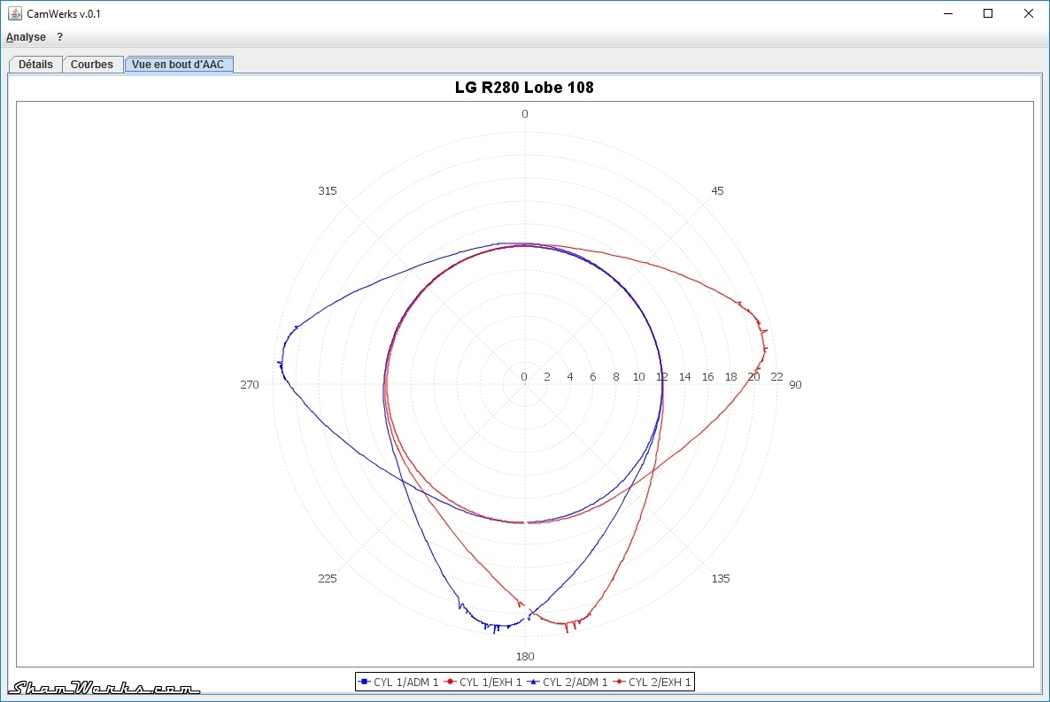
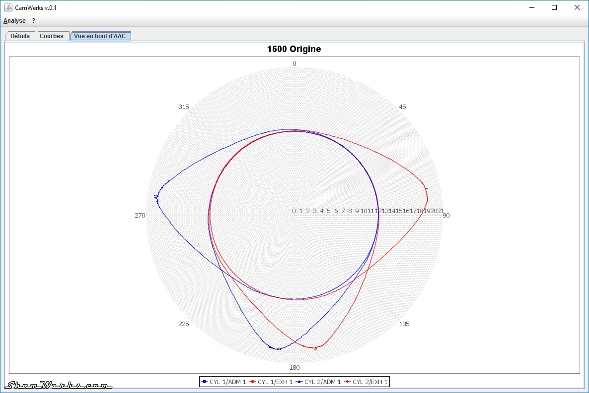
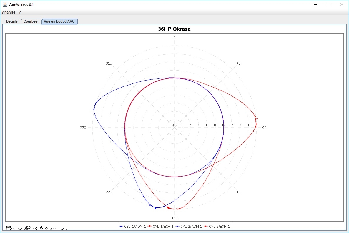
Cams profile view, as seen from the camshaft's axis :
Deducing the profile shape from the measures was tricky, I've had to ask for help to a math researcher friend of mine! Thank you JB for the tea-biscuits-and-math afternoon! 😉
The result is not perfect, and can only be correct using a flat faced lifter ; it'd be incorrect with a round one (as they are on 36hp), or roller-type lifter.
I also added a curve smoothing algorithm (a simple sliding window average) so that the cams shape would look nice ; long story short, remember this view is provided "as is", don't look too much into it.
Versions history :
- 2017-04-05 : version 0.1 : first version released.
- 2019-11-27 : version 0.2 : update to fix a bug that made the measuring process crash after just 1 step of the motor (when trying to round a double variable that turned out to have value set to "infinity" for some reason - gotta have to find out the root cause at some point)
Results
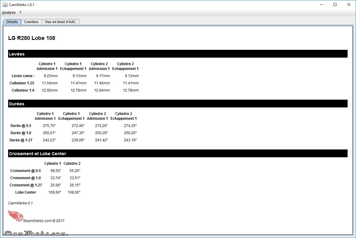
Following are the resulting data out of the different camshafts I had laying around...As you can see, the first tab presents a Detailed Report giving different informations : duration re. lift, maximum lift, valve lift re. rocker ratio, lobe center and overlap.
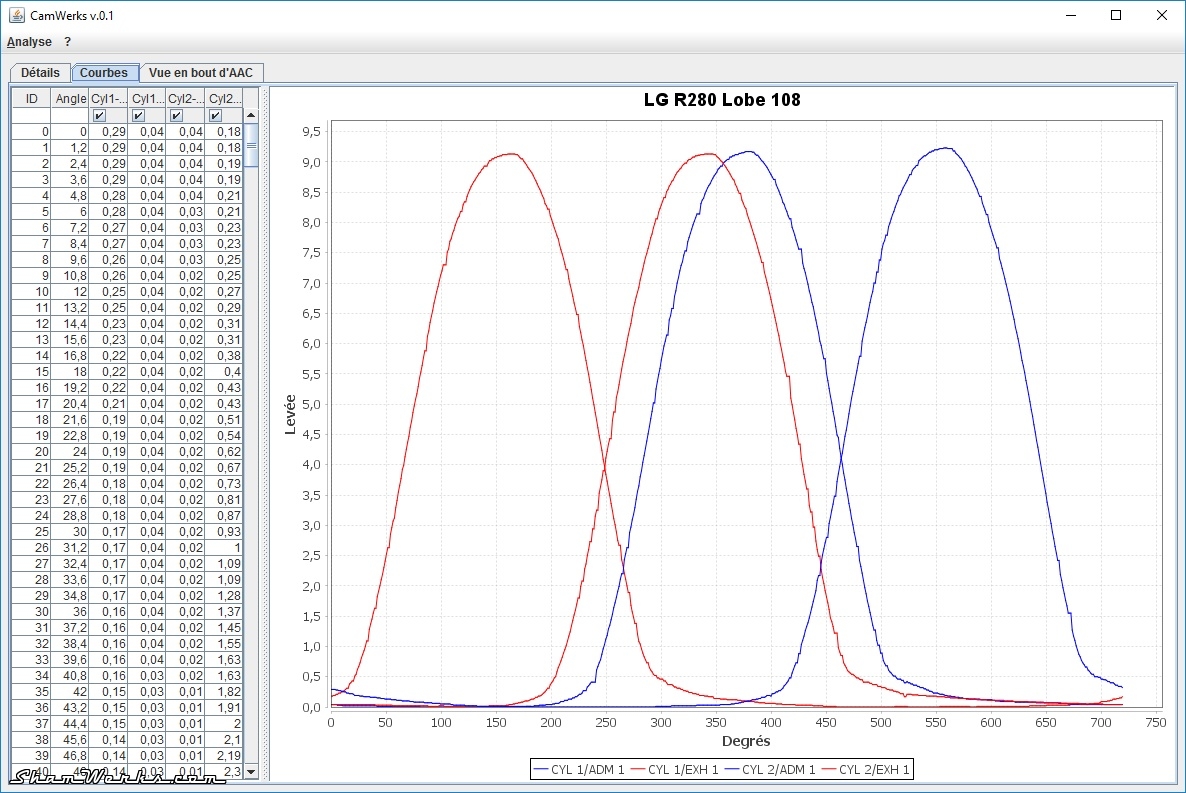
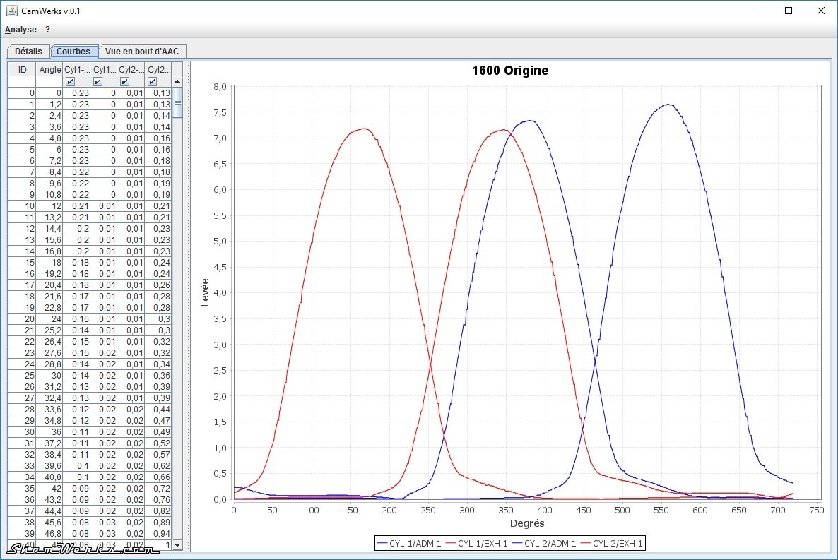
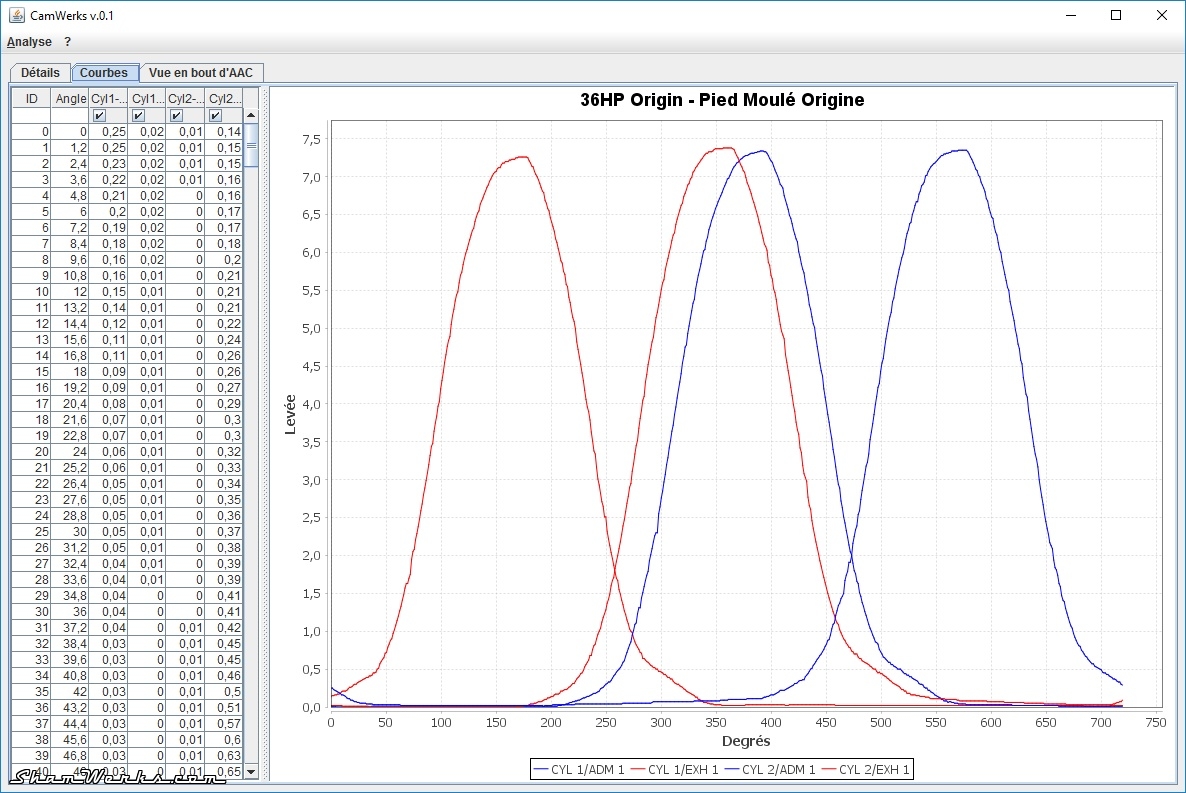
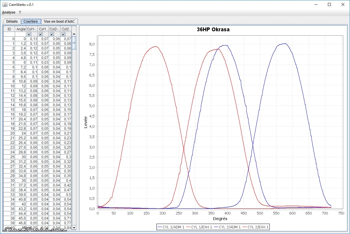
The second tab show the lift curves of each cam ; the third and last tab is an axis view of the cams profiles.
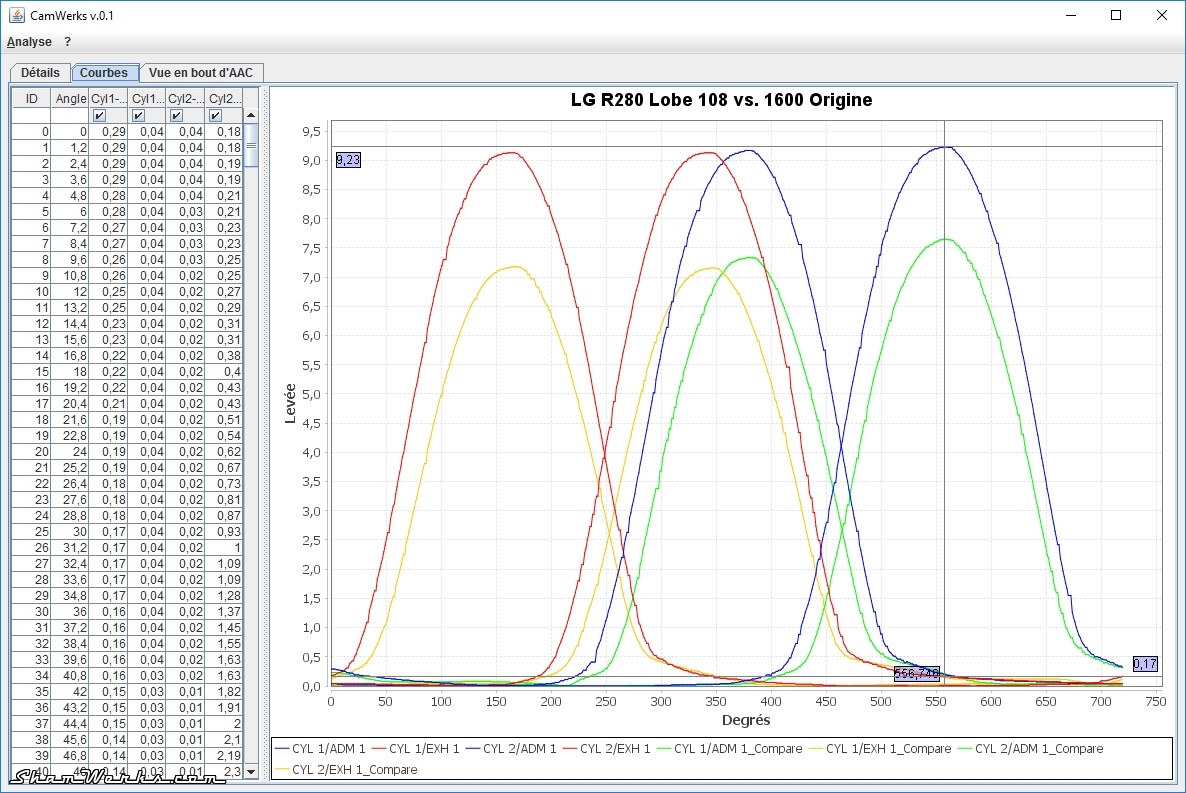
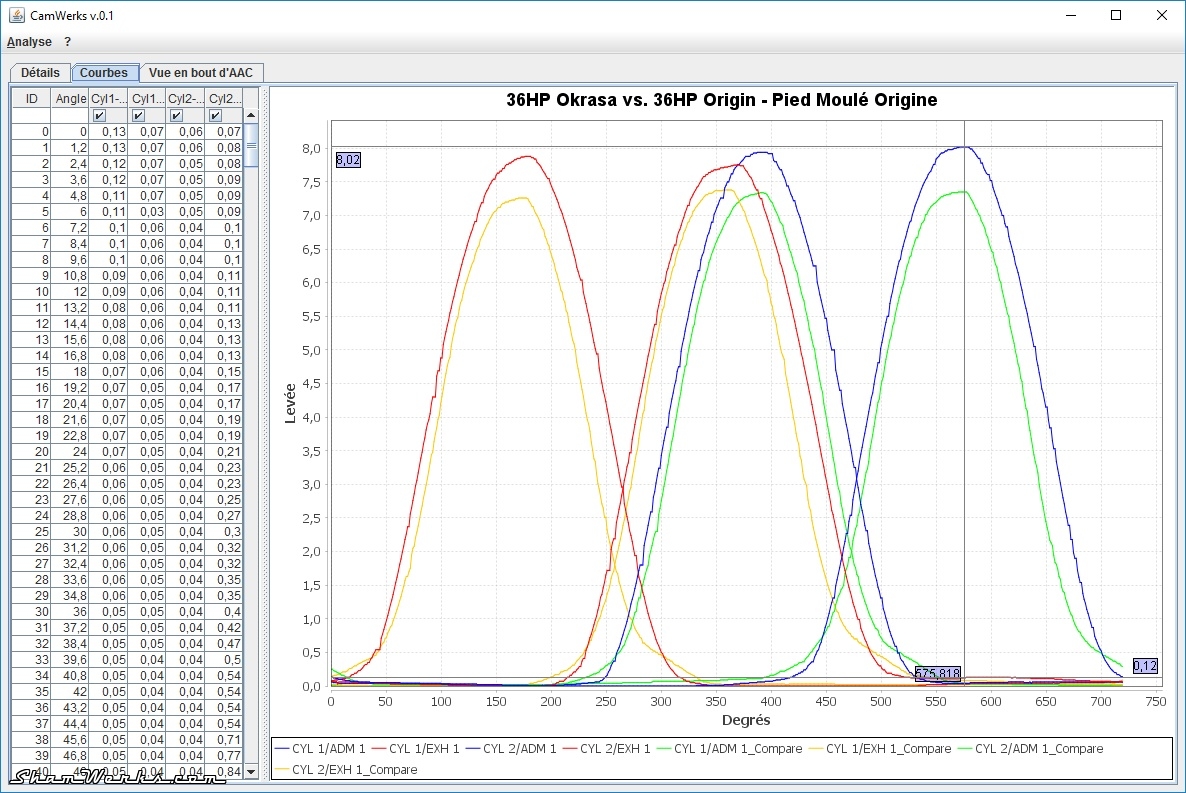
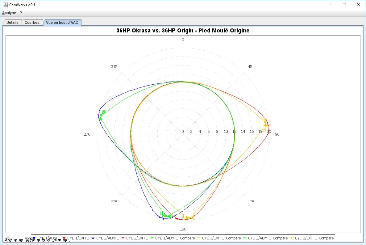
Last but not least, I've added an option in the software to compare two camshafts. It allows to surimpose the curves from two different camshafts in order to visualize their differences.
L&G R280 Lobe 108°
Here we go, let's put my brand new L&G R280 Lobe 108 camshaft to the bench, and compare the output with the datasheet provided with it! 😊Here's what I measured with my bench :
| Datasheet Value from L&G |
CamWerks measured value | ||||
|---|---|---|---|---|---|
| Cylinder 1 | Cylinder 2 | ||||
| Int. | Exh. | Int. | Exh. | ||
| Cam lift | 9.19 mm | 9.23 mm | 9.13 mm | 9.17 mm | 9.13 mm |
| 1.25 rockers lift | 11.49 mm | 11.54 mm | 11.41 mm | 11.46 mm | 11.41 mm |
| 1.4 rockers lift | 12.87 mm | 12.92 mm | 12.78 mm | 12.84 mm | 12.78 mm |
| Intake duration | 242° | 242.23° | 241.42° | ||
| Exhaust duration | 242° | 239.09° | 243.19° | ||
| Overlap duration | 26° | 25.68° | 26.15° | ||
| Lobe Center | 108° | 108.6° | 108.0° | ||
The biggest delta I found is about exhaust duration : -2.91° / +1.19°, that's a bit much... I'm gonna double check the way I reckon the angle of the "peak" on the cam. Sylvain from Classic-Store (whom did not hesitate spending 20 minutes on the phone with me, while I only sent them a quick technical question... Fantastic customer service, thanks!) told me that it's not uncommon to have 1 to 2 degrees of difference on a camshaft, due to the original pattern/jig wearing off. So, not such a bad result in the end.
I've not yet managed to calculate the opening advance and closing retard... This information depends on the position of the camshaft in relation to the crankshaft (well, actually, the TDC and BDC), and I've not yet managed to integrate this into my formulas! (for now!)
I also do not have the "commercial duration" : well, this value is of no real interest actually, the lift at which it is measured is arbitrarily chosen by manufacturers. Only the durations at 1mm and 1.27mm loft are relevant to compare camshafts to one another... On mine, the advertised 280° duration is reached around 0.48mm lift.
Stock 1600cc camshaft :
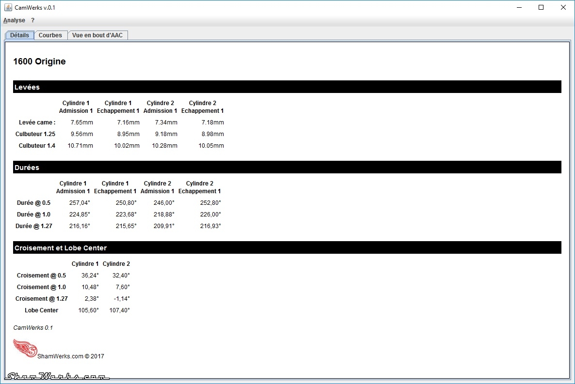
By the way : the stock values shown here are from VW forums (Flat4Ever and TheSamba), I'm not absolutely sure of the source... If you have any better figures, I'd gladly update my table!
| Stock VW value | CamWerks measured value | |||||
|---|---|---|---|---|---|---|
| Cylinder 1 | Cylinder 2 | |||||
| Int. | Exh. | Int. | Exh. | Int. | Exh. | |
| Cam Lift | 0.754 mm | 0.724 mm | 7.65 mm | 7.16 mm | 7.34 mm | 7.18 mm |
| Intake duration @0.50 | 250° | 257.04° | 246.00° | |||
| Exhaust duration @0.50 | 250° | 250.80° | 252.80° | |||
| Intake duration @1.27 | 214-218° | 216.16° | 209.91° | |||
| Exhaust duration @1.27 | 214-218° | 215.65° | 216.93° | |||
| Lobe Center | 108° | 105.6° | 107.4° | |||
Please note that the measured camshat is a used one, therefore the result may somewhat vary.
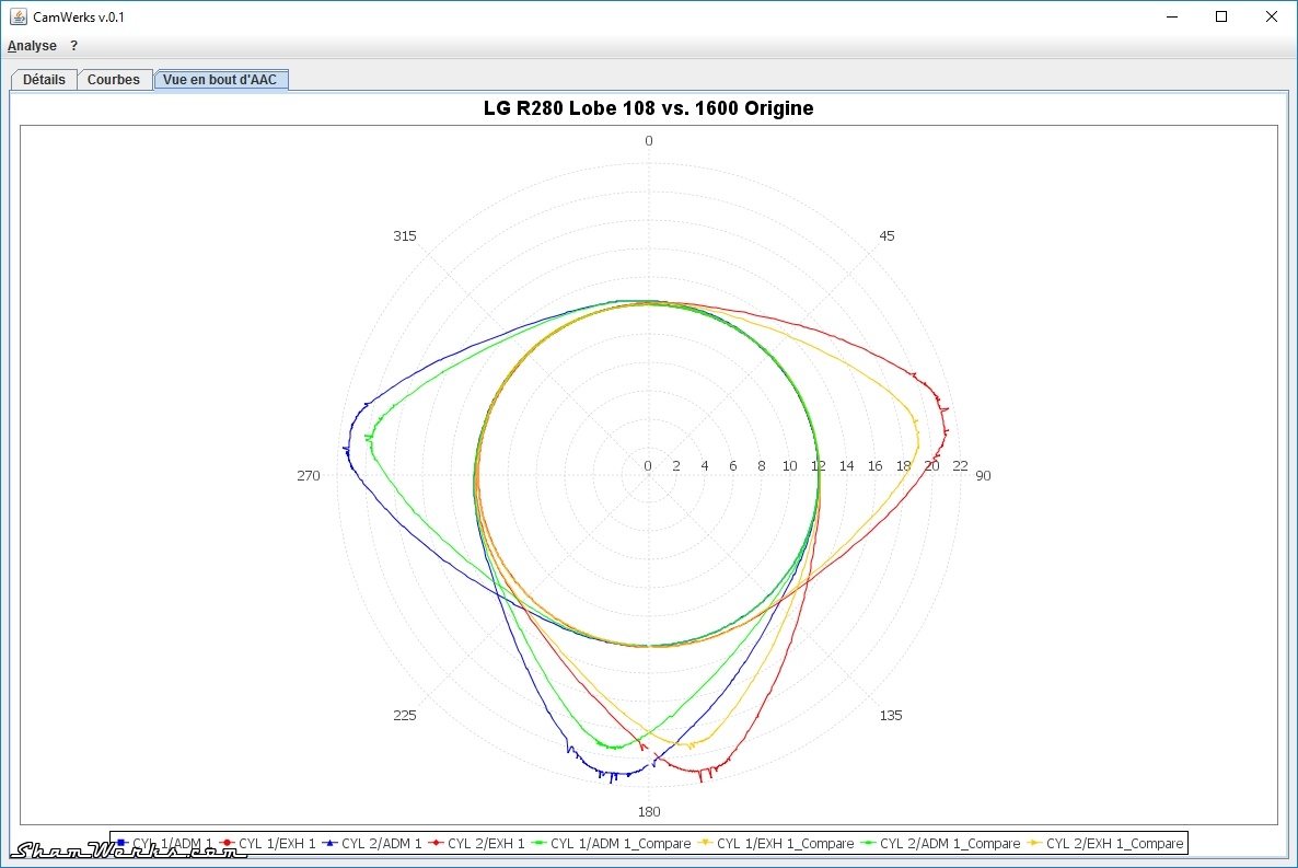
Comparing stock 1600 with the LG R280 Lobe 108°
Stock 36hp
The cams views doesn't look great towaards the peaks... My original measures probably weren't clean.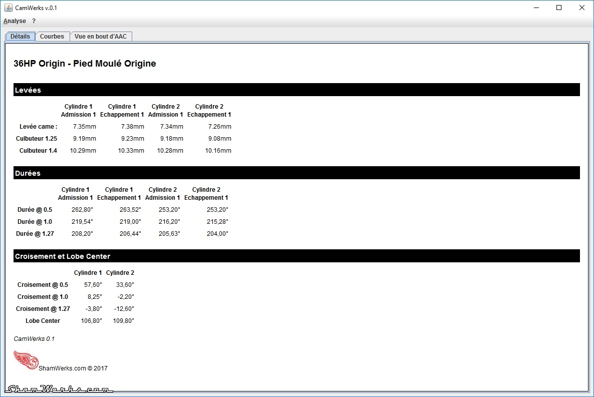

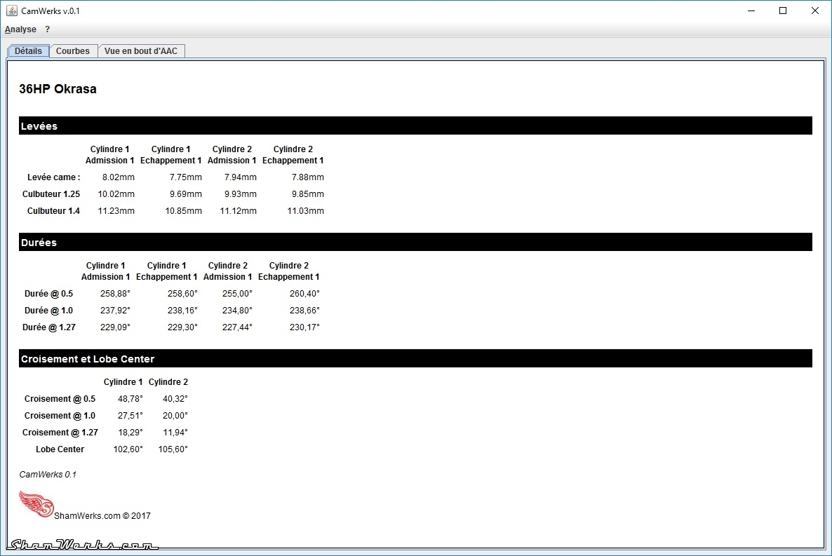
36 hp "Okrasa" / Joe Ruiz :
Comparing stock 36hp and Okrasa version
Conclusion and future evolutions...
I'm not completely satisfied with the lifters I modified to mount on the caliper... They're not exactly parallel to the camshaft (wel, the angle grinder isn't know to be an accurate tool, right?), so they do not rest perfectly flat on the cam... Gotta do somethin'bout it.And on the software side, I'd like to add the durations on the cams view...
The results are consistent and can be reproduced (I gaet only up to 3 hundredth of a millimeter difference between to measures) : for a prototype I threw together on the side of my workbench, I'mm really happy with the result! Yet I've no way to know how accurate my measures are : for that I'd need the output of an actual, professional bench, and compare the output with wine... I may have a solution to do just that, I'll let you know. 😁
Anyway : keep in mind you should see this bench as a prototype, a "proof of concept", not a finalized project... But it already does the job ; hopefully it will give ideas to some of you! 😁
FAQ / Questions & Answers
1. can you provide support for your software? / Can I use a L298xxx driver? / Why do I get an XYZ error when running your software? I can't get to communicate with the arduino?
I am sorry, I can only provide a very, very limited support. Between my job and my family duties, I have very limited left free time. Several people have tried to make their own CamWerks bench, but failed due to a lack of any previous experience with electronics, software or arduino... And I have not been able to help them.It is not such a complicated project, but you'll need some previous arduino experience if you don't want to end up in a dead end with the PC communication part. I highly suggest you first spend some time on Youtube learning the basics of arduino programming before you start this project.