Kitty Injection : 1776 part. 2
Here's an article that took its sweet time before publishing... Anyway, things are going forward - slowly, but still forward!
Crankcase
I kept working on the case :- All edges are smoothed,
- Casting marks are removed,
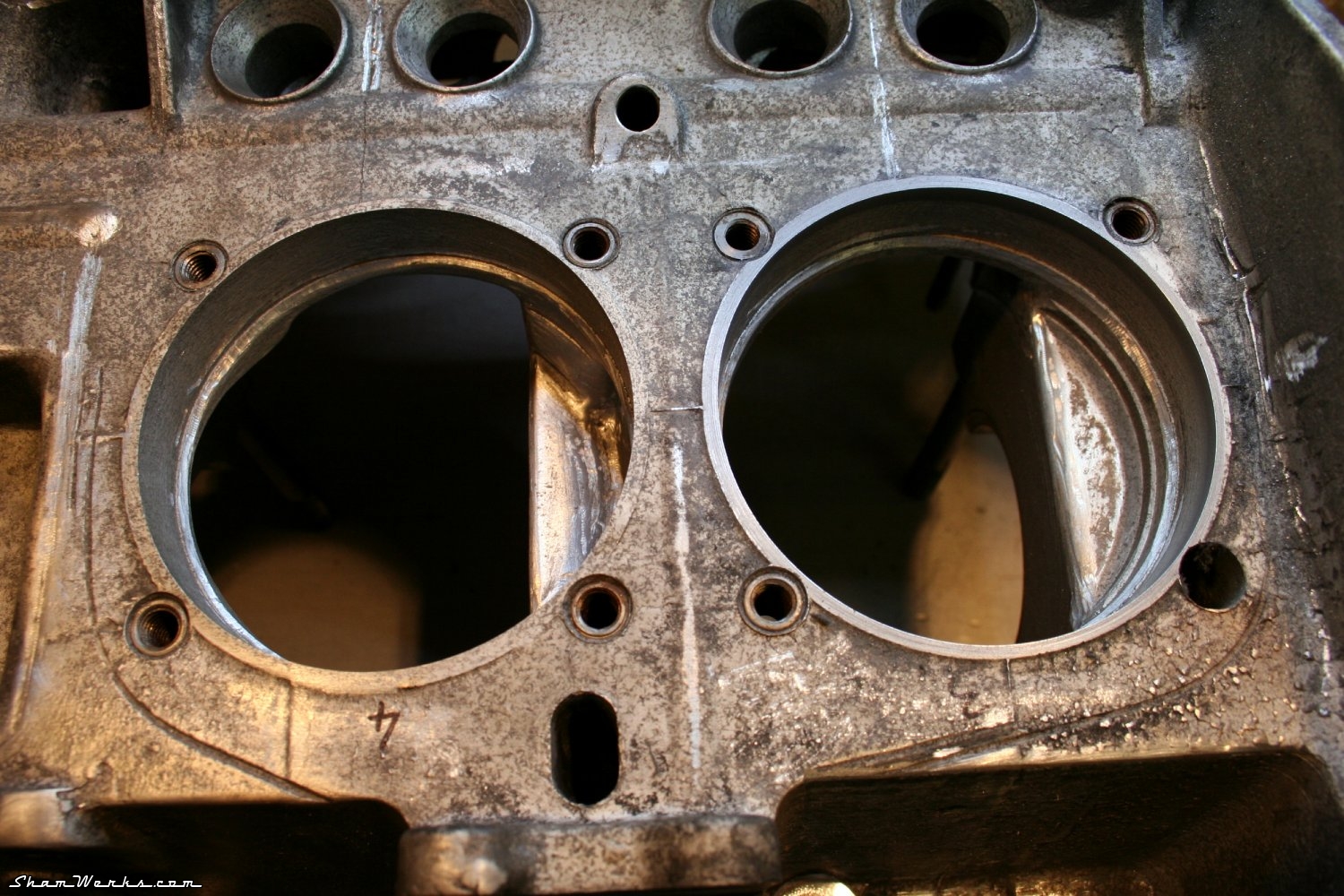
- The ventilation holes between cylinders 1&2 / 3&4 are widened (the three fingers rule!) and smoothed,
- the oil return hole at the bottom of the partition with the distribution gears is enlarged,
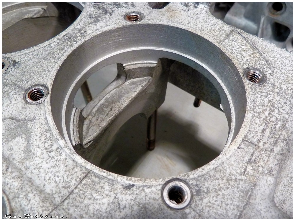
- the ventilation above the central bearing is enlarged.
The global idea is twofold : first, enhance the air flow inside the crankcase to avoid over-pressure, second, ease the return of the oil to the bottom of the case, in order for it to go back in the oil circuit (the oil remaining on the inner faces of the case is useless!).
Smoothing the edges also helps preventing concentration of constraints in the material, and the cracks that could result from them. Well, to be honest, I'm not really too concerned about that on my little 1776! 😁
As a comparison, here is one of the ventilation ports before smoothing... 😉


For the case's exterior finish, I used a fine rotary abrasive brush (on the pneumatic grinder, this baby gotta turn fast!). The objective was just to remove the oxidization and remaining muck after its previouss chemical cleansing...
Berg Conversion
I had my mind set onto using head washers an nuts around the case ("Gary Berg conversion") : the thick washers (4mm) and the 15mm nuts allow a tighter torquing of the case perimeter (2.7mkg instead of the origin 2mkg), leading to a more rigid crankcase.But to do so, one needs first to spot face the case for the washers to lay flat on the material... As I did not really want to go
In order to do so, you would first need the right tool, a 22mm counterboring bit with a 8mm pilot tip (actually fellow enthousiast KY260, advised that Ø23mm is even better, as the washer may be a bit tight with 22mm). Not an easy to find tool, but I finally found it on eBay : a set of 23mm cutters, with two CM3 tool holders and 4 14.4mm pilot tips. At 44€, that was a steal! 😉
As I don't have a mill, I want to use that tool with my drill press ; in order to do so, I lathed down one of the CM3 tool holders to give it a cylindrical end instead of the conical morse one. I also lathed one of the pilot tips down to 8.5mm (that hardened steel was very, very hard to lathe!).
Finally, I have the correct tooling, let's give it a shot!


So, here we go now, same procedure on my actual case. It's actually quite a quick process, except the ones below the case ; some Dremel work was required to free the way for the cutter.


Unpluging the oil galleries
In order to thoroughly clean the oil galleries, and by doing so avoid that some gunk would screw up all the nice work do so far upon engine's first start, you must un-plug the galleries. The operation isn't that difficult if you're careful : first center-punch the plug, then drill it with a 3mm drill bit ; then force-screw a sheet metal screw in that hole, and pull on it with an inertia hammer.Since I did not have an actual inertia hammer, I thew one together with what was available around the workbench... I'm actually pretty happy of that recycling of an old rear-drum 36mm nut. 😁


Cleaning and plugging back the galleries
So, now that the galleries are un-plugged, it's time to clean them, and find a way to plug them back after!Here's the tools of the trade for these two steps...
I ordered plugs from Torques.co.uk (great address I already got fuel fittings from). These are conical NPT 1/8"x27, 1/4"x18 and 3/8"x18. They are anodized aluminium, really nice products ; to be installed with Loctite 577 pipe sealant ; make sure you have the imperial size Allen wrenches to tighten them in!
As for the cleaning of the galleries, any means are good. Myself, I'm first using the compressed air to get rid of as much shavings and dust as possible ; then bottle brushes, shotgun brushes and pipe-cleaning brushes... And lots of brake cleaning fluid ; some WD40 can be used too, to help removing any hardened oil sticking in the nooks and crannies.
To make it a bit easier, I like to mount the bottle/riffle brushes on my cordless electric drill, and then go back and forth in the galleries while turning full speed ; that's the way to go, galleries end up all nice and shiny! (sorry, no picture about it, I could not manage to get a proper picture inside the oil gallery)


Prior to taping, you first need to drill the holes : here are the drill bits sizes you'll need for that :
- 1/8" plug : 8,5mm drill bit (11/32"), going 15 mm deep
- 1/4" plug : 11mm drill bit (7/16" ), going 26 mm deep
- 3/8" plug : 14,5mm drill bit (37/64" or 9/16"), going 25 mm deep
You need to be cautious while taping, as it's conical. As per the depth, you need to go little by little : tap a little, test fit the plug, tap a bit more, test fit the plug, et cætera until the plug sits flush with the case when tighten. To make it easier/faster, once the first plug of a given size is tapped, I make a mark on the tap for the next ones! (see previous picture, red marker stripe on the tap)


So here we go gain, NPT 1/4"x18 tap, directly in the gallery without any prior drilling (inside diameter is correct). Half a turn ahead, quarter turn back to get shavings ou, and repeat... The plug will be tightened in the gallery with its dose of Loctite 577 pipe sealant again.
Running in the Cylinders
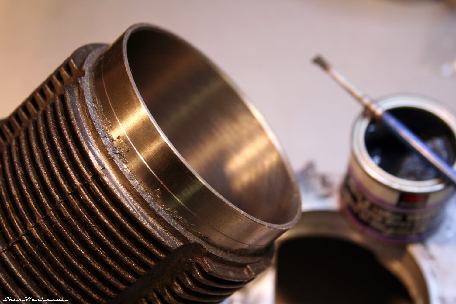
I then hone the cylinders on the crankcase, to make sure they seat correctly. Some may think it's not necessary, but as I'm trying to do things right...So here we go, honing compound applied with a small brush at the bottom of the cylinder, a fw back-and-forth movements (3cm to the left, 3cm to the right, repeat). Doesn't need much, few minutes per cylinders are enough ; you can see the matte finish on the picture below, showing propper hoining. It's also a good way to check the cylinders aren't resting on the case savers, but well onto the case itself (it not, some Dremel action would be required).
In my case everything looks fine on all 4 cylinders, perfect, validated. Next.
Camshaft
Out of the box, the cams edges are razor sharp, which may damage the lifters upon engine's first start. So I lightly smooth them down with my Dremel and a sanding drum. It doesn't need much, just smoothing down that angle a bit ; I finish it off with some 600 grit sandpaper with a drop of oil.The journals are polished with some 2000 grit sand paper (a worn-out ScotchBrite pad would work too), to remove any imperfection and promote the oil film. If you use sand paper though, make sure you thoroughly clean the part after, as grit particles may get embedded in the material (well, that's more true about the soft material of bearings han the hard steel of the journals!).


Finally, a thorough cleaning/degreasing of all the parts (brakes cleaning fluid, acetone), and assembly, torquing the screws at 25nm, with a drop of Loctite threadlock (the stronger, red one - you really don't want these to get loose!). The notch in the camshaft (that drives the oil pump) has to be aligned with the mark on the gear.


Oil pump
The oil pump is a modified model, prepped by Feller Service (a french perf shop) : it's a Shadek 26mm base, machined to add a couple of O-rings around it (to prevent leaks and cavitation). The pump body and gears are rectified so that the gears are perfectly flush with the body (checked with my trustful rectified ruler).The output is already plugged, with the full-flow output on the anodized black, CNC aluminium cover (tastefully engraved with the name of my fav parts dealer! 😁).
More information about this pump on Feller's blog (in french only I'm afraid) ; actually if you give it a close look, my pump cover is somewhere on the last picture, on the right hand side... 😁
Anyway, here's a really nice, highly recommended product, and made in France for once!


And that's it, enough for the oil pump, it's ready to install!
To be continued soon! Published on 30/06/2014 / 0 commentaires