Milling machine: restarting and CNC conversion
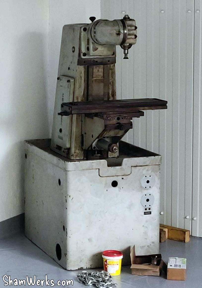
In keeping with the long tradition of my projects taking forever and a half, I bought this Crouzet Valence FC100 milling machine in 2016; since then, I haven't had the time or space to take care of it.
But it was time for a change; I have projects for which it would be very useful. And I don't need a 450kg paperweight. 😁
So go grab some popcorn buddy, we're off on another long article - the longest on this site to date, surpassing the previous record (it was Küby: Back on the road again)... 😉
Warning: if you have some experience in this area, you might see some things that will make you scream at your screen. Sorry buddy, I've never had a milling machine before, this is my first time doing all this (#IhaveNoIdeaWhatIAmDoing), I'm learning as I go, I'm bound to make some stupid mistakes.😁😁
My goal has always been to convert this machine into a CNC: I've been preparing for this since I bought it, and over the years I've found a good part of the necessary equipment second-hand (drive, box, circuit breakers, contactors, buttons...) or on sale (stepper motors, toothed pulleys, drivers, controller, ball screws, etc...), between LeBonCoin, eBay, the classified ads on the Usinages.com forum, and AliExpress. Luckily, because all that new at full price would have cost me an arm and a leg excluding taxes (i.e. an arm, a leg, and a kidney including taxes). 😁
This machine was at one point in its life, stripped of its original screws/verniers/handlebars on the X and Y axes, so I don't have too many regrets about modernizing it to get it running again. And since this is a model that originally didn't have automatic advance on the X (the FC100s could have it, but not mine), I have even less qualms about sticking stepper motors on it.
I'll try to do all this step by step:
- Restart, electrical cabinet, new three-phase motor with frequency inverter + Ball screws on X and Y
If I can already mount my ball screws on the X and Y axes, and change the motor, the machine will become usable and will help me to make the parts for the rest... - Motorization of the X and Y axes
Addition of stepper motors, and connection to the CNC controller, itself connected via Ethernet to MACH3 on the PC. - Z-axis motorization
The Z-axis motorization will be the most complicated to carry out, due to the weight of the assembly to be moved...
Come on, let's jump in! 🍿🥤
Disassembly and Deep Cleaning
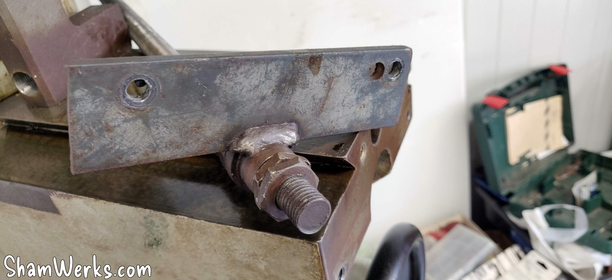
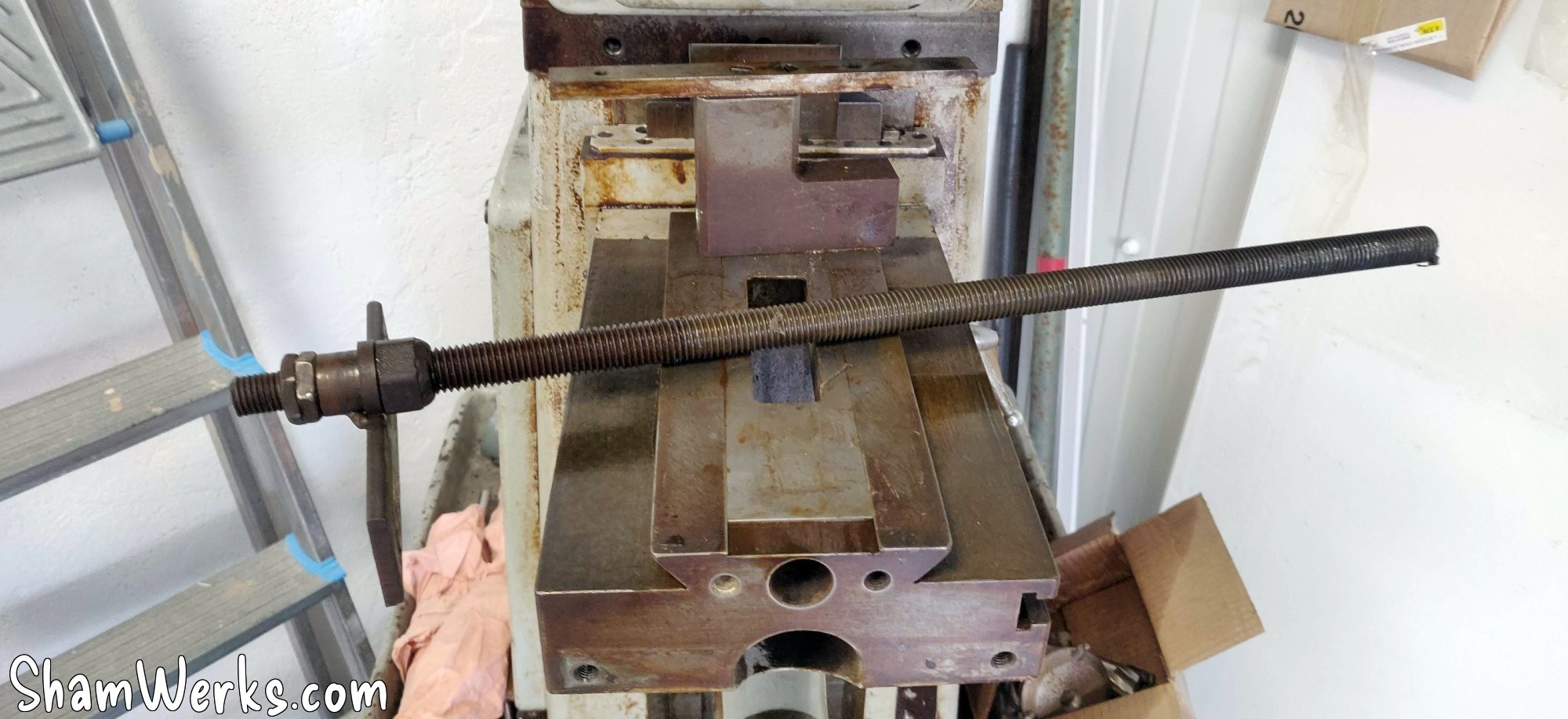
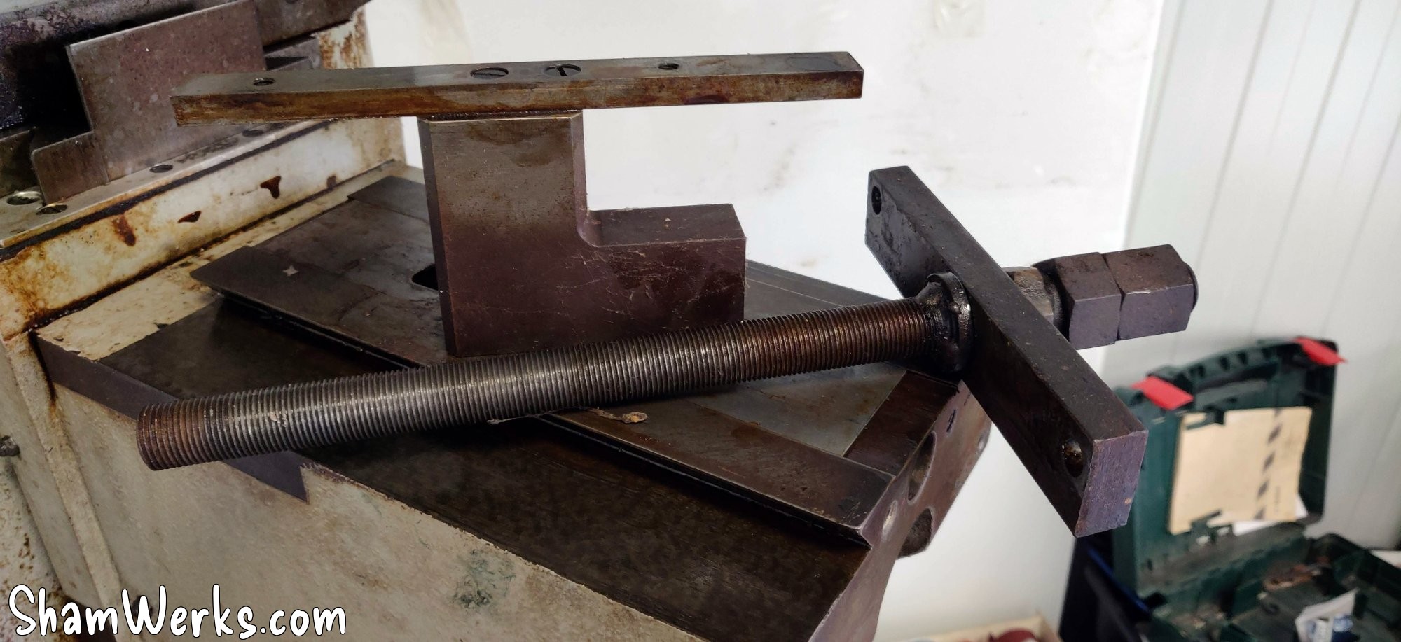
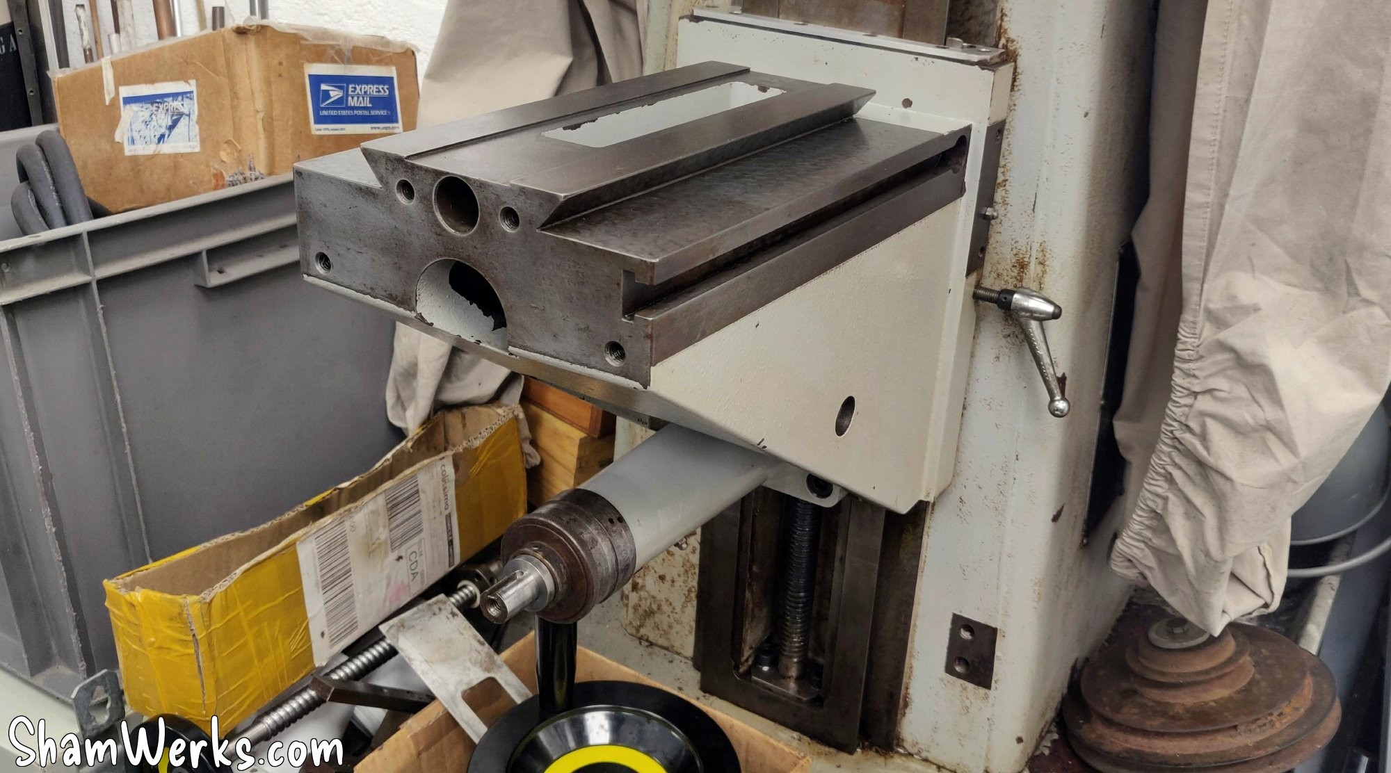
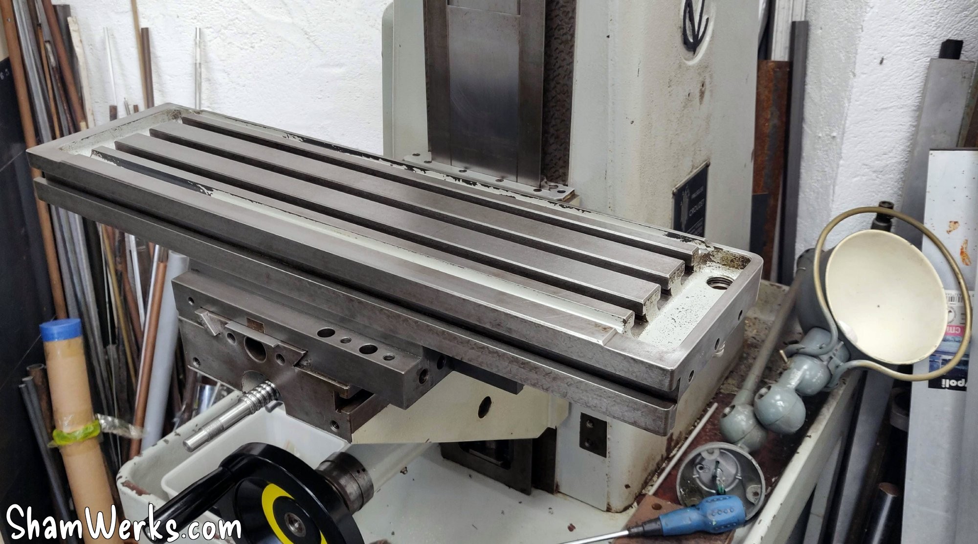
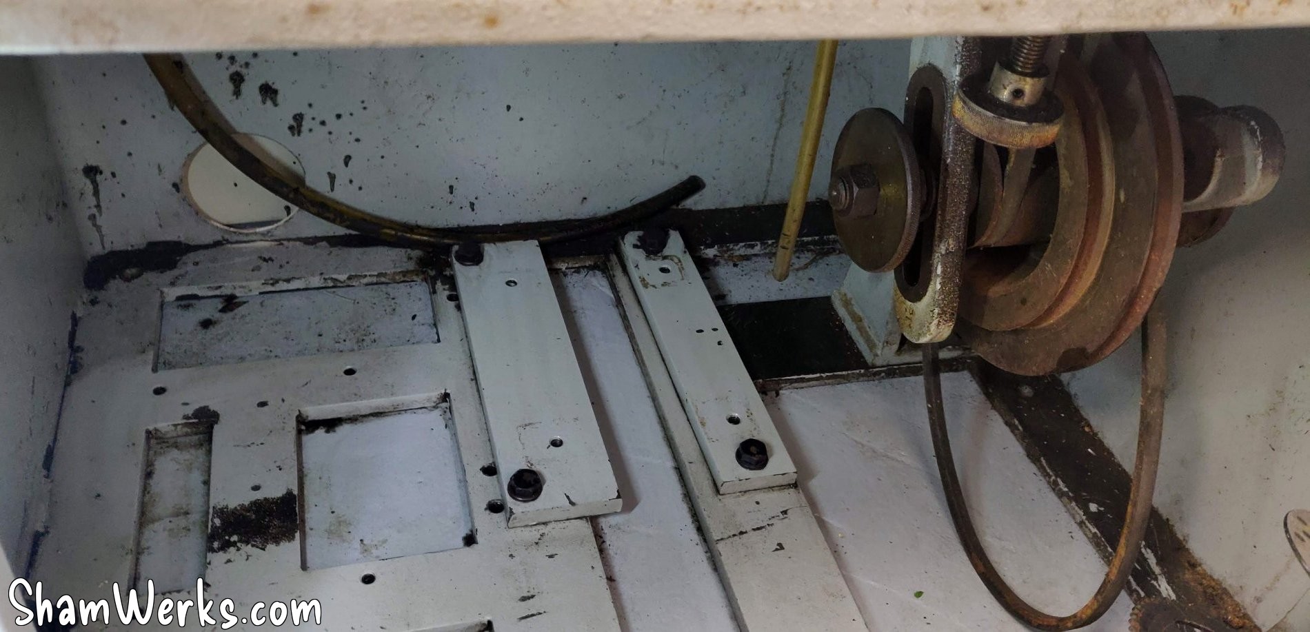
I'm taking everything apart to assess the damage... The original trapezoidal screws were replaced at some point in the machine's past, with disgusting mechanically welded supports... Everything will come free, and I'll carefully clean the rest to remove grease and rust.

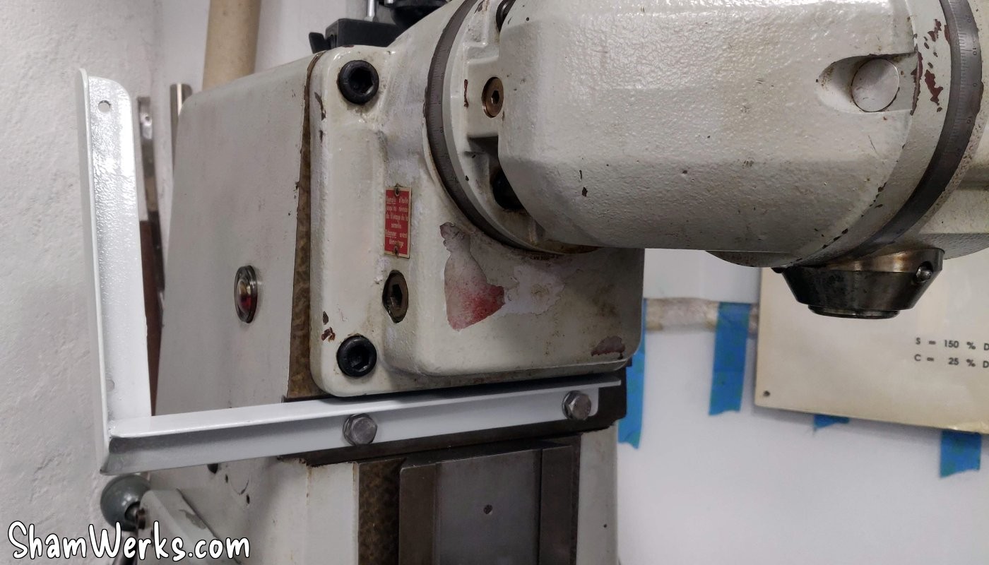
After a thorough cleaning with a Jex pad + WD40, I noticed that the original paint is in pretty good condition (except for a big patch on the right side of the receiver) under the layer of hardened oil. It will stay like that for the moment, I will see later about repainting... Or not, I like its patina too.
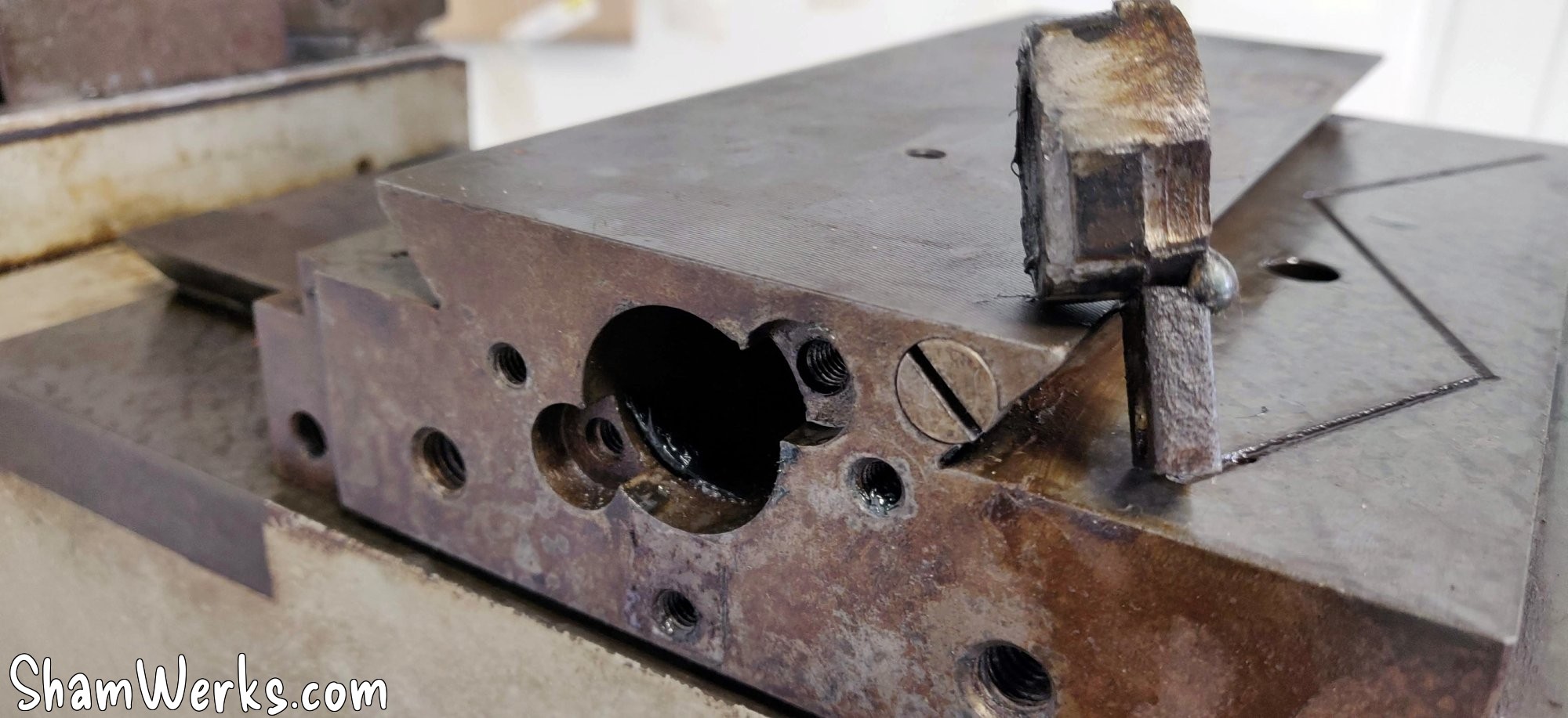
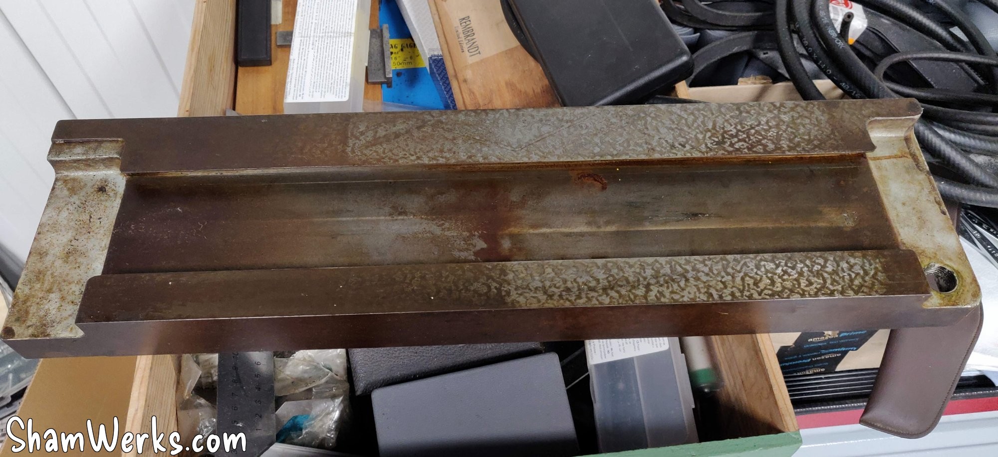
The transverse carriage is pretty clean, its scraped surfaces in good condition. After a thorough degreasing, it spent a few days in a tank of EvapoRust, just to get rid of the superficial rust that was starting to appear here and there, it comes out as good as new...
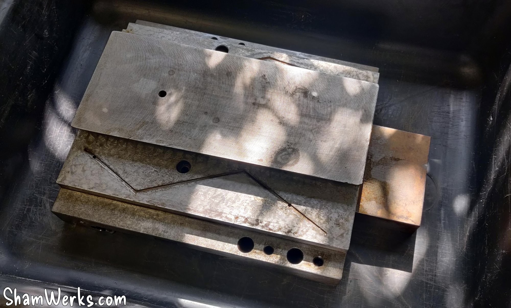
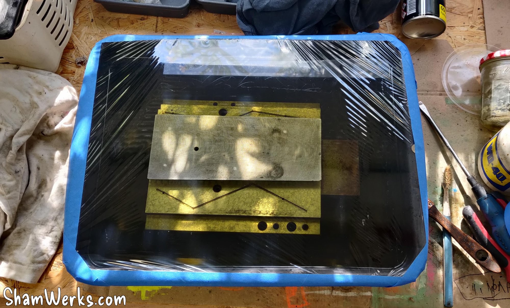
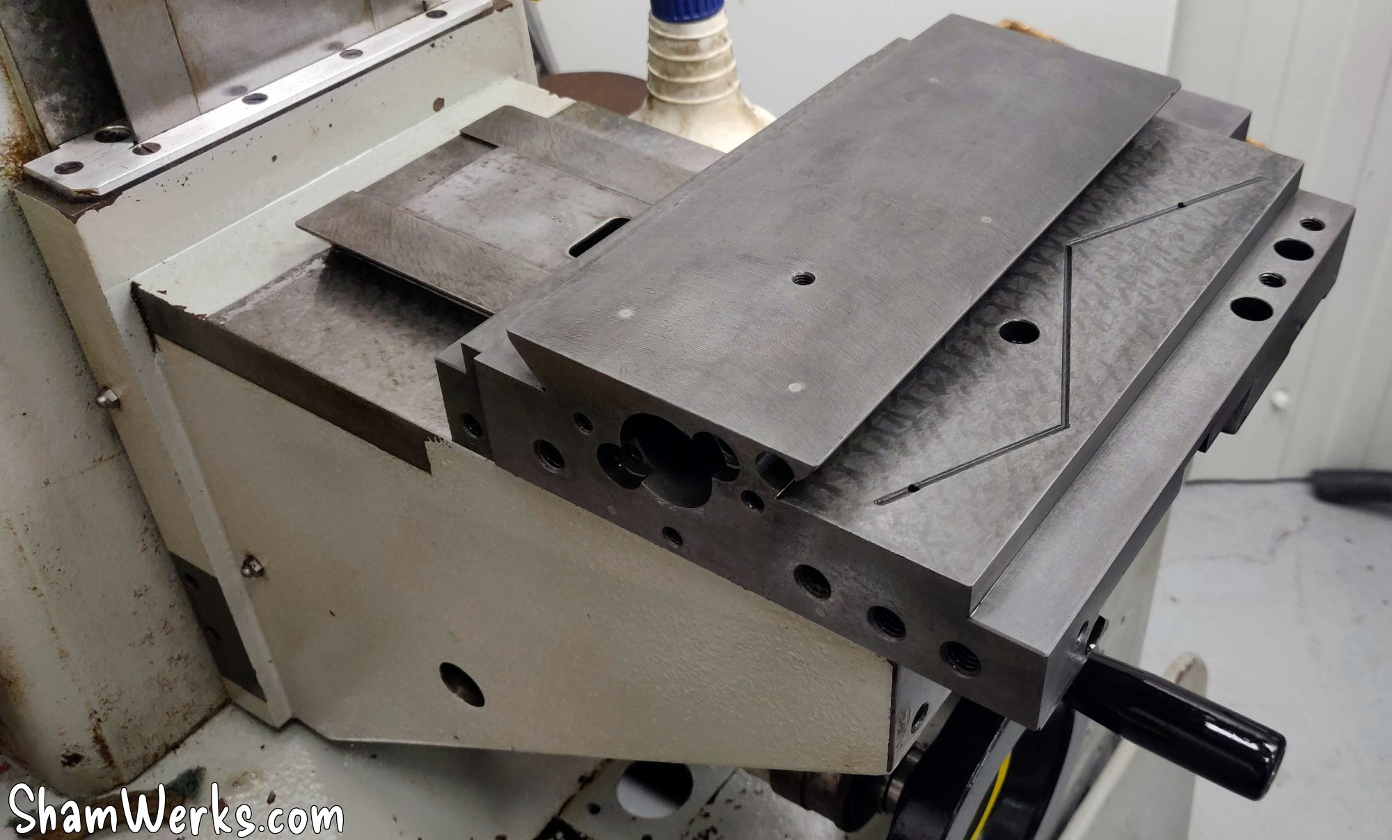
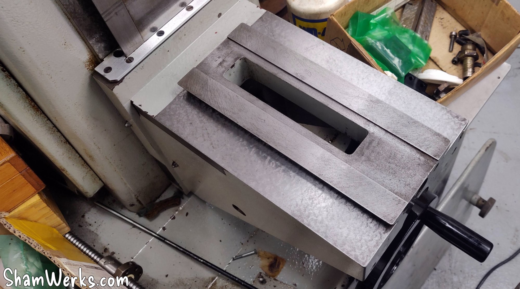
Under the table you can still see the scratch marks, but only where the table has remained motionless for a long time, in contact with the trolley... I tried a bath in EvapoRust here too to remove the rust, the result is pretty good. Validated!
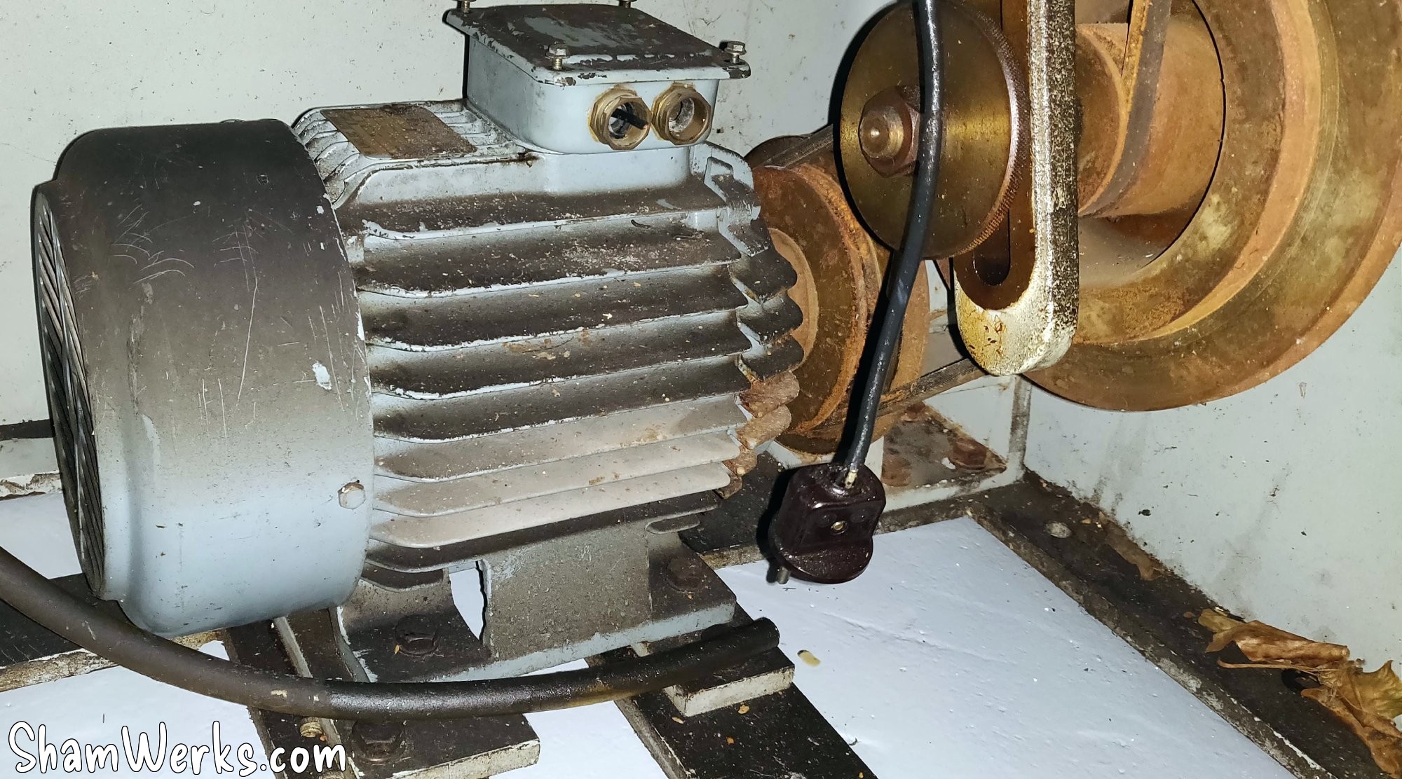
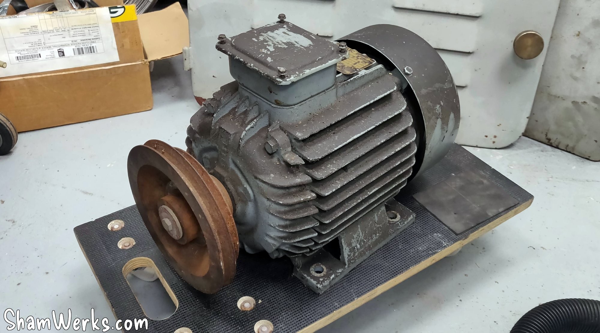
Spindle motor
The original motor looks in good condition (3hp/2200W), but it's a 2-speed Dahlander taking 400V only... Which is not compatible with what I want to do, namely power it via a single-phase to three-phase 220V frequency inverter.
Actually, there could be a modification to be made to the winding to use it, but it's long and complicated... It's simpler and cheaper for me to change the motor directly, Chinese motors are pretty cheap nowadays.
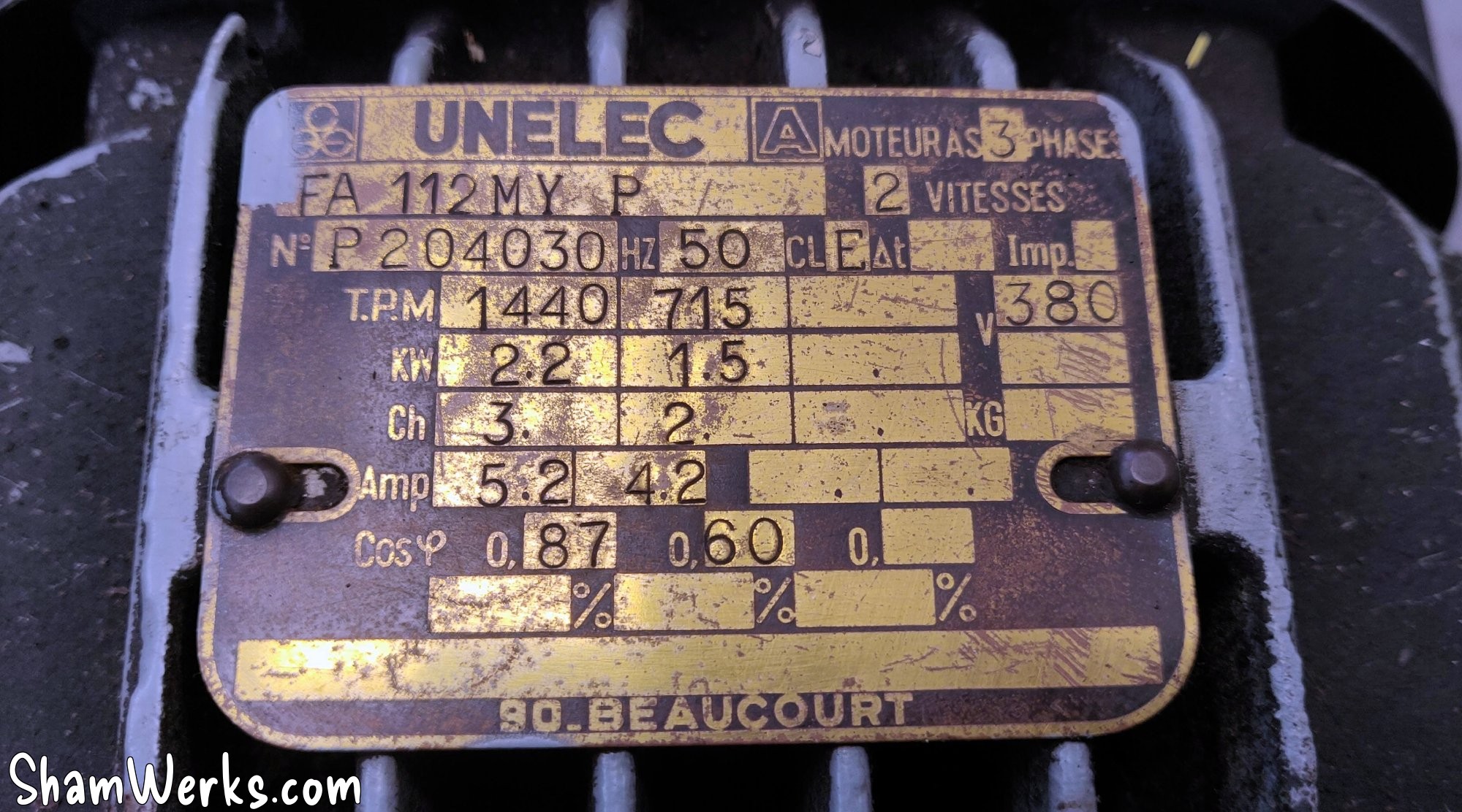
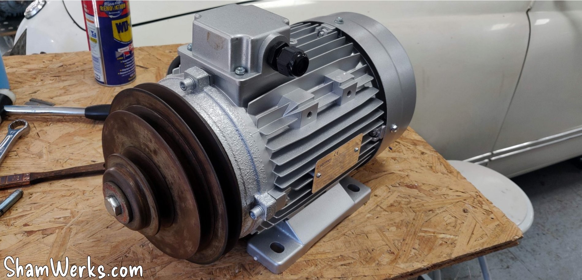
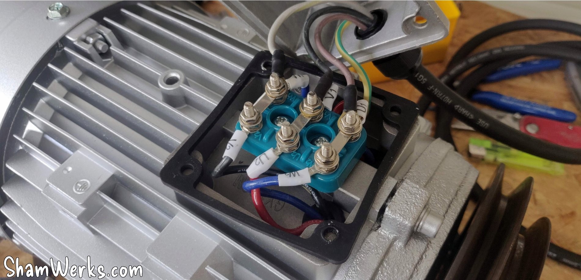
So I order one from "pompe-moteur.fr"; I had already gone through that company to replace the motor of my bandsaw (ah, I just realized that I had never shown you that one...), and it turns out that they have a motor that corresponds to the specifications of the original one: 2.2kW/3hp, 1500rpm, 230/400v, even its holes positions flange limit the work to fix it in the milling machine.
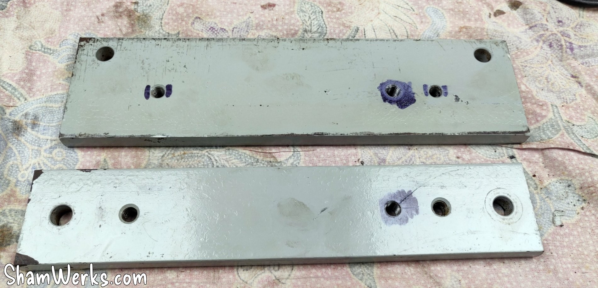
I then take out the original Dahlander, I drill/tap two M10 holes in the original flanges, I take the opportunity to clean all the grease/oil/belt dust, and I reassemble everything, with the original pulley which fits without any modification.
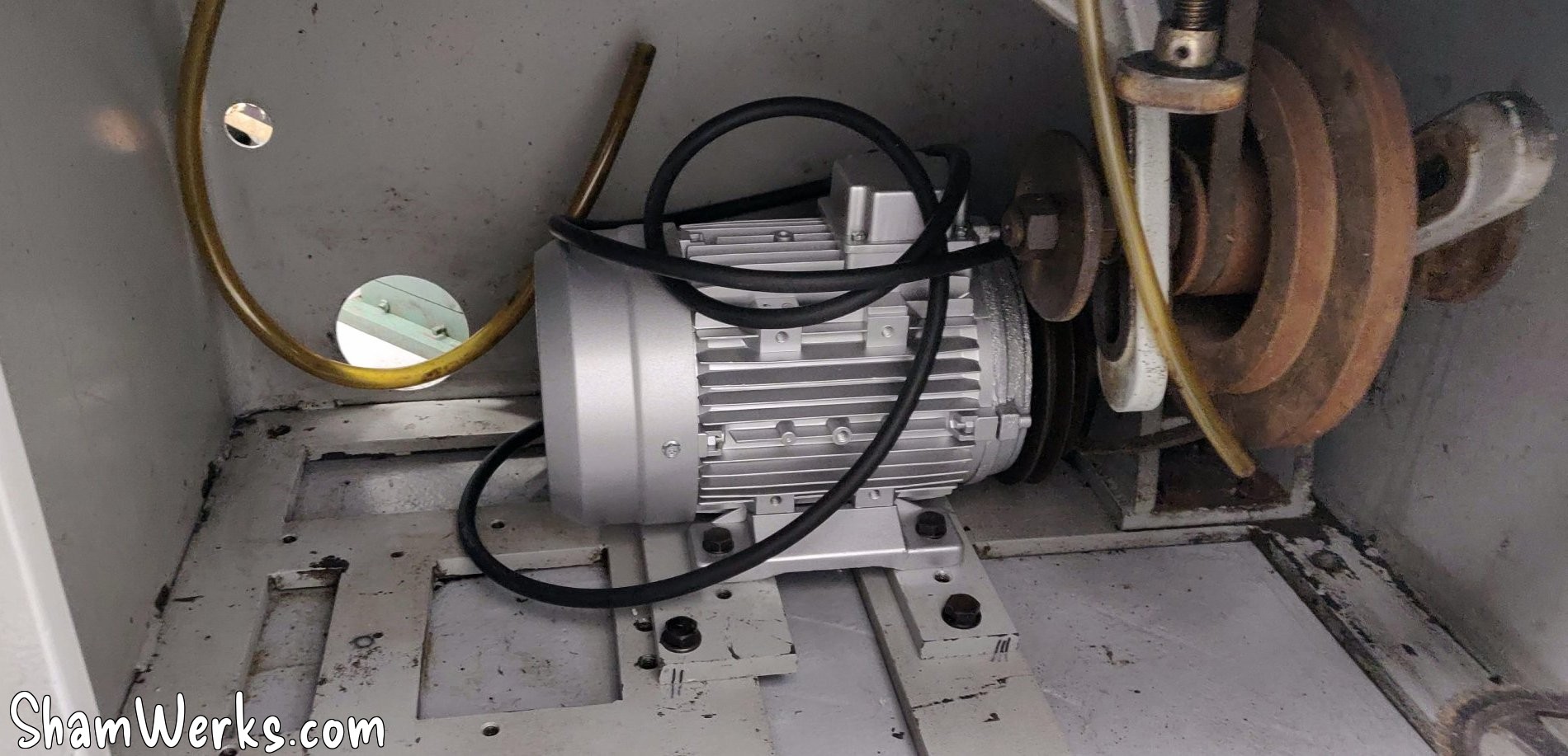
Well, put like that, it sounds simple, right... In practice, I threw my back out while removing the original motor, and I spent 10 days completely blocked. Go ahead, laugh, I deserve that. 😁😁
As I write this article, looking at the pictures I realize that I mounted the pulley on the new motor backwards! I'm going to correct that... Damn I'm dense sometimes! 😁😁
Electrical cabinet
Since one shouldn't joke around with three-phase current, and to be able to use the machine safely, I want a proper electrical cabinet. So this part took me quite a bit of time to get right.
🔧 Design/Diagram
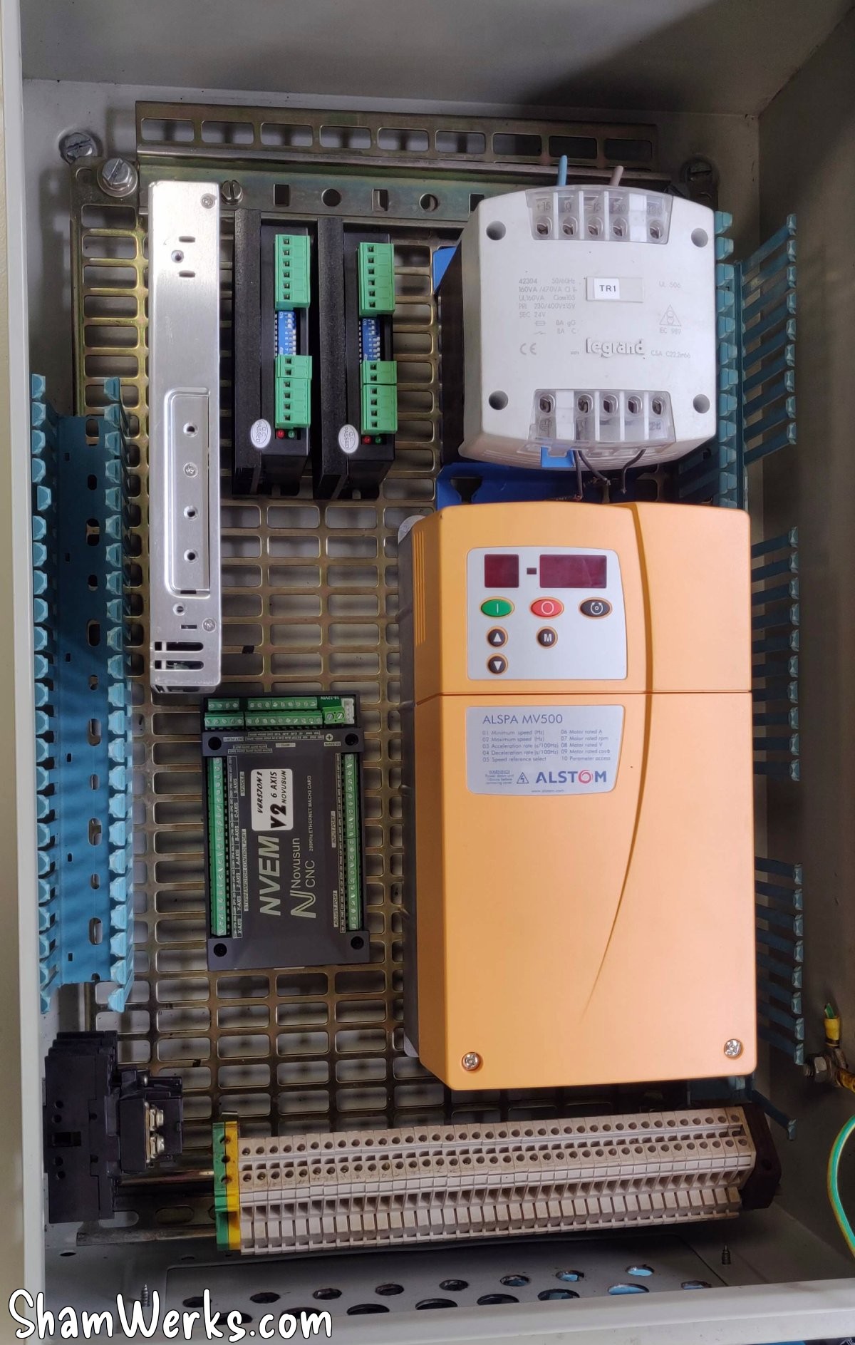
To power the spindle motor in three-phase, I use a Mono-Tri frequency inverter (220V Alstom ALSPA MV 500 inverter, 2.2KW, bought second hand at a good price, beautiful baby of 6 kilos...): you get 220V single-phase in on one side, and it comes out as 220v three-phase on the other, of which we can adjust the frequency, and therefore the speed of the motor.
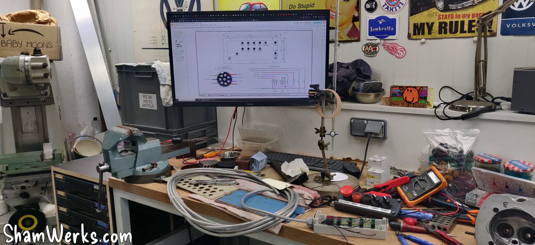
I worked for a while on the electrical diagram (thanks to the members of the Usinages.com forum for their advice!), and here is the result - it's Google Slides, use the arrows to navigate the diagrams - or click here to open it in a new tab.
The ayatollahs of industrial design will surely have something to say (blah blah the colors, blah blah the format is not iso, etc.), but at least I manage to find my way around it, and that's what matters to me. 😉😂
In these slides you will find: power circuit, data circuit, the organization of the sockets under the cabinet and the pinouts of the aviation sockets, just for reference, because I like everything to be documented precisely, it makes maintenance easier later. Besides, all these diagrams will be printed and stored in a plastic pocket inside the cabinet...
Again, keep in mind that this is my first time doing any of this, I don't claim to tell you how to do it, only how I did it. 😉
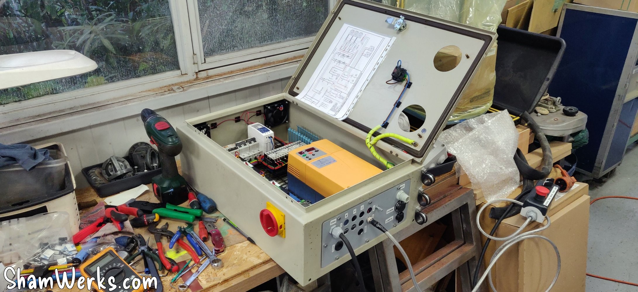
🔧 Enclosure
The cabinet itself is 600mm x 400mm x 210mm - already 13 kilos empty, so quite chunky, though in practice, a bit bigger would have been more comfortable...
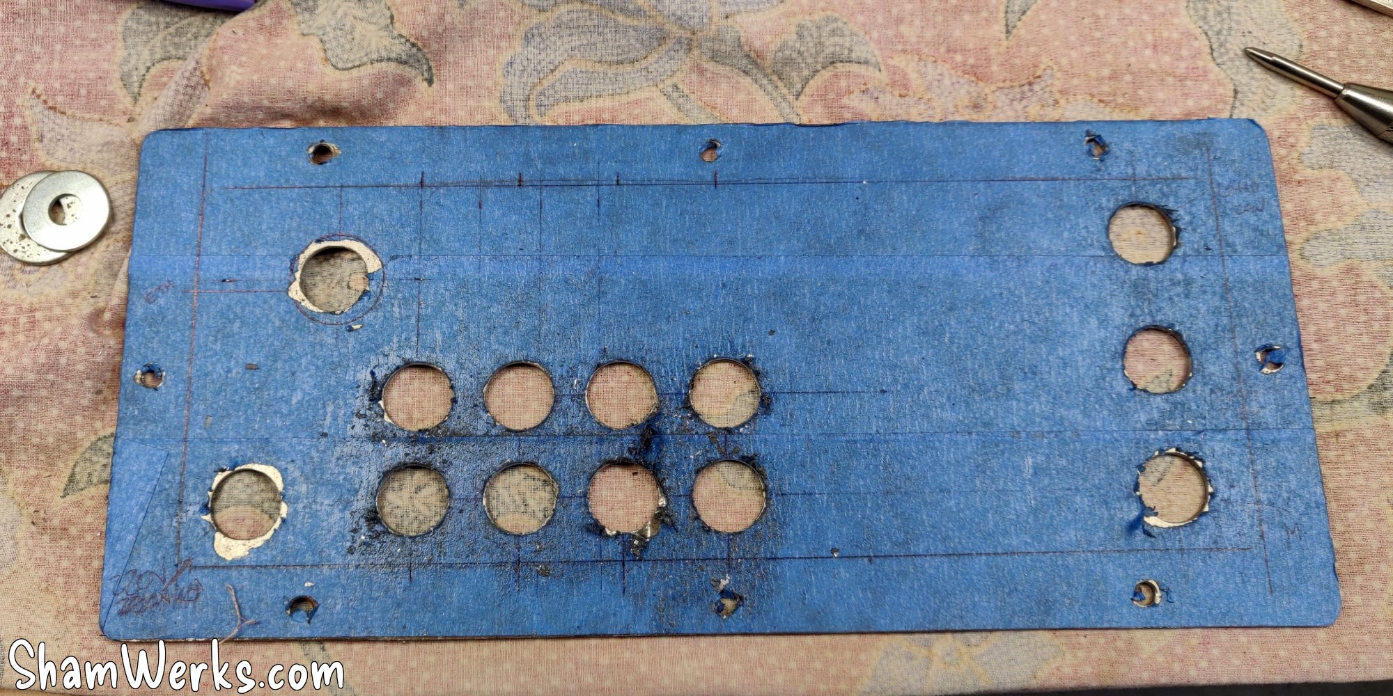
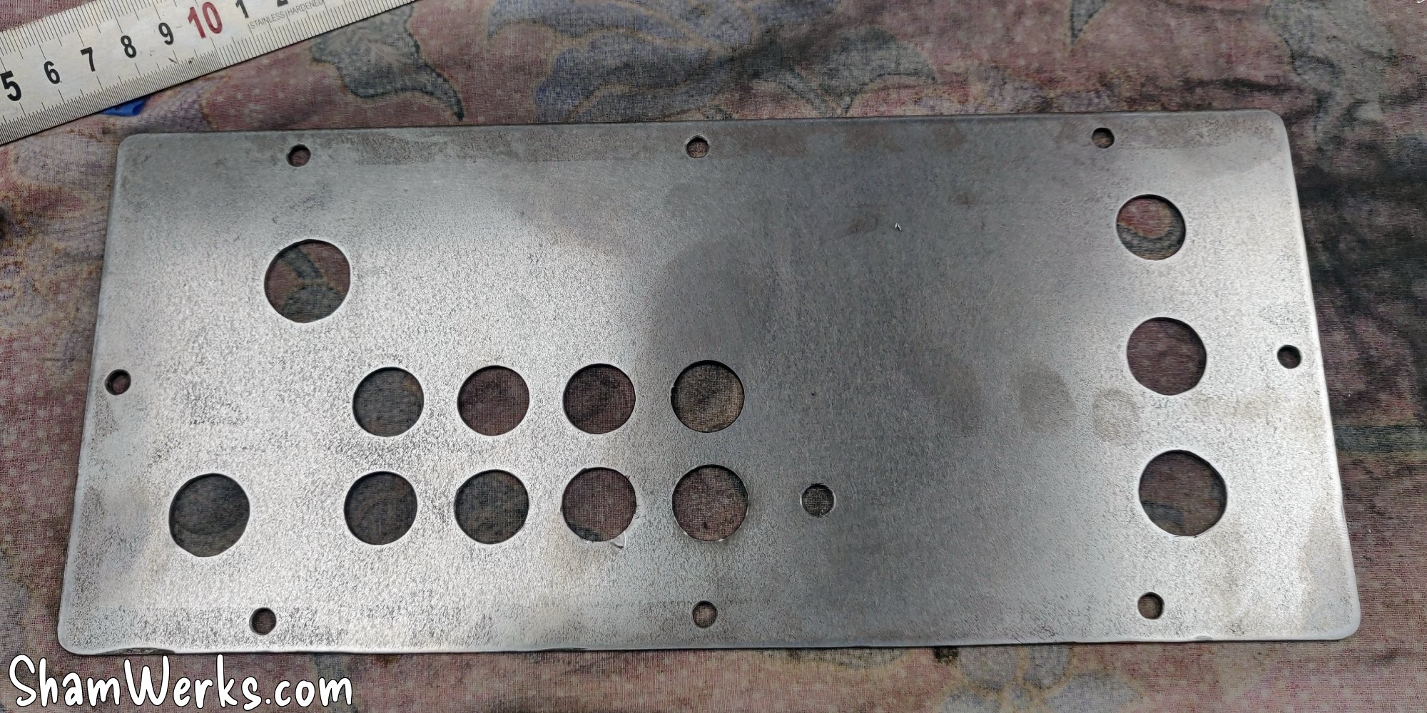
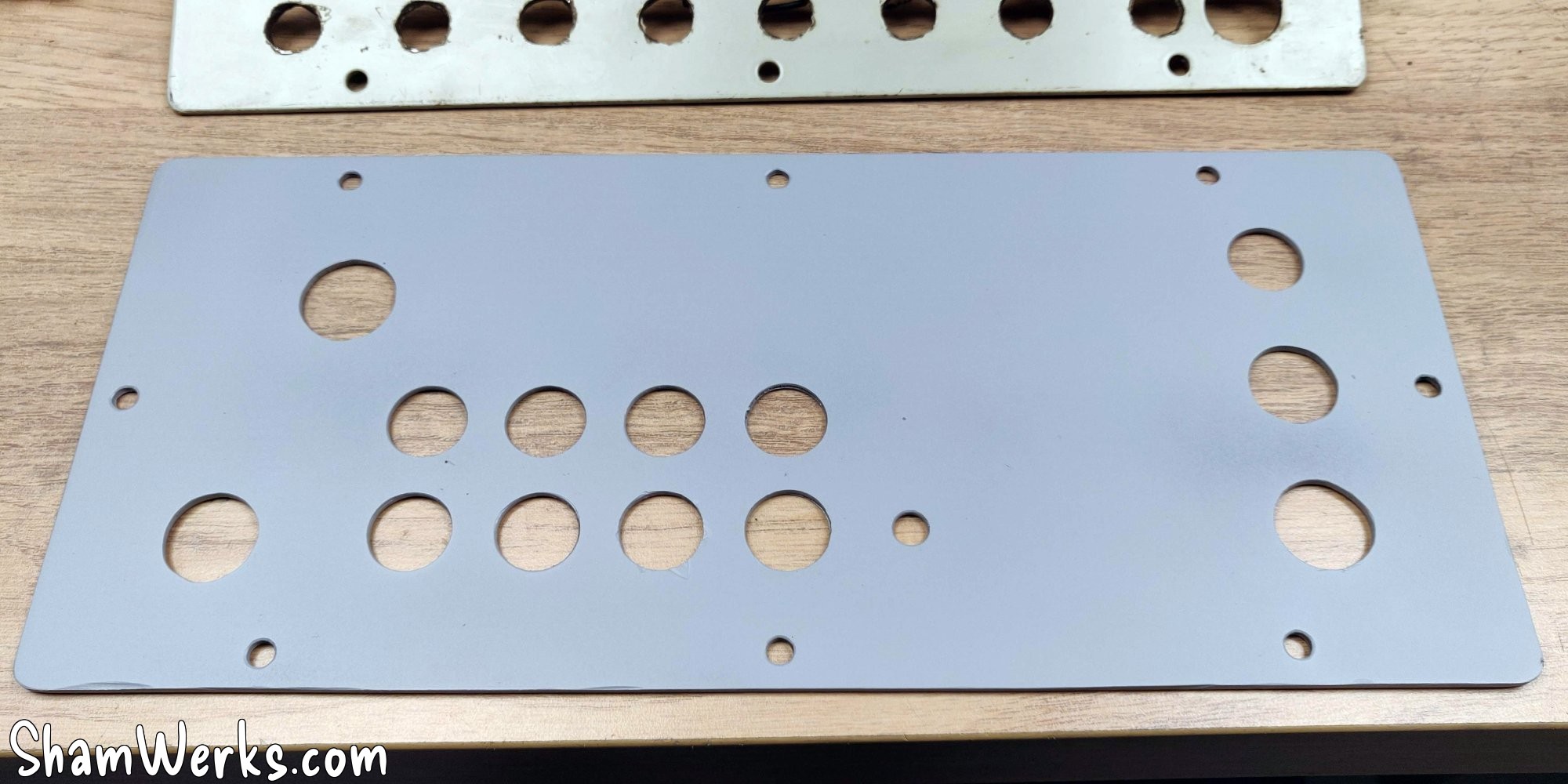
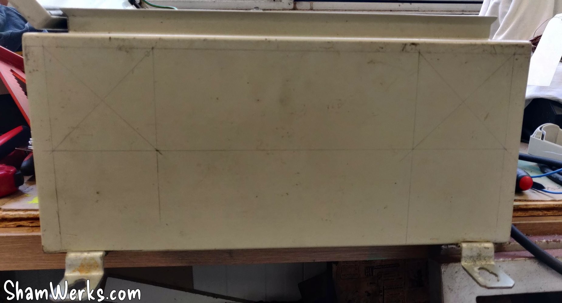
The cabinet is second-hand and so obviously, the bottom plate where all the connections arrive has been drilled in all directions. I cut a new one out of a 2mm steel sheet, drilled holes, painted to prevent rust, and done. Well, not completely done, I had to add one last hole because I changed my mind, choosing a "closed loop" stepper motor for the Z, so it was necessary to be able to send the encoded data back to the driver - we'll come back to that later.
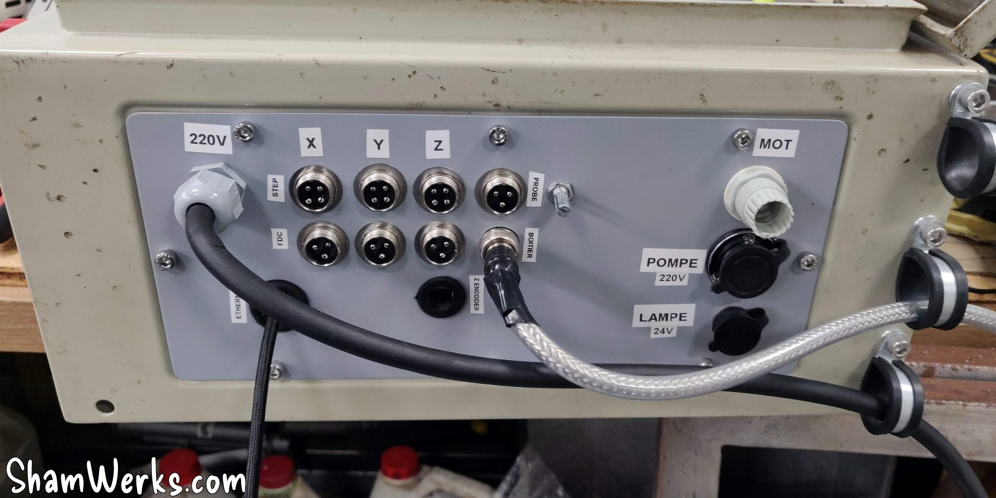
I use aviation connectors to be able to disconnect the cabinet easily if necessary. Only the 220V input, the 3-phase output for the motor, and the Ethernet port of the CNC controller are exempt.
On the right side underneath, I install 3 P-Clips using crimp nuts, to support the weight of the cables. I find this more mechanical than relying on the avia plugs, with the risk of pulling on the solder joints.
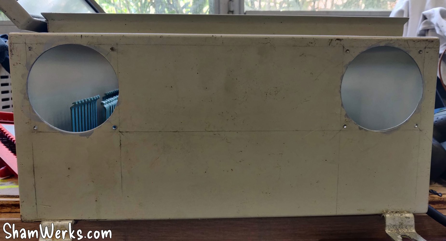
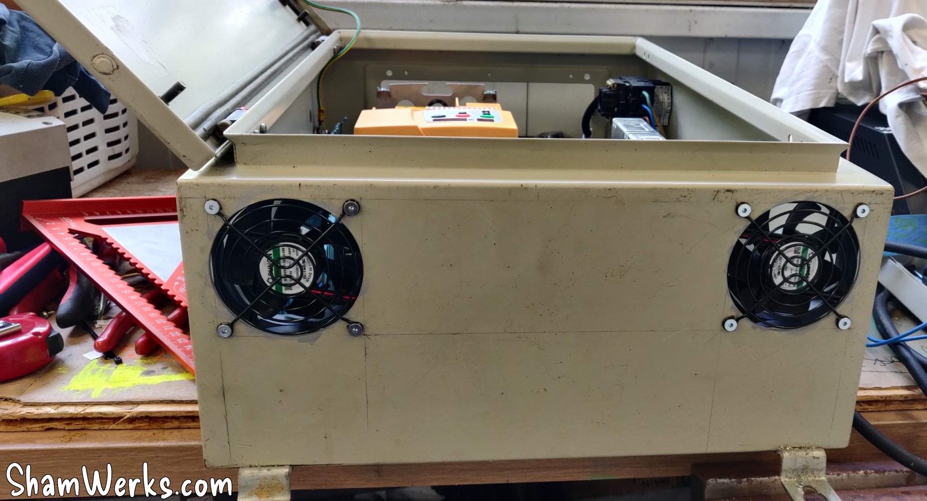
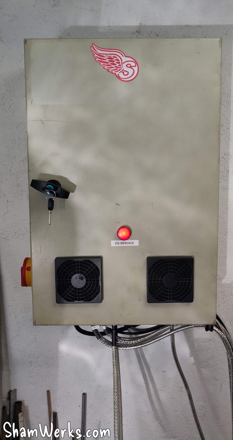
As inside the cabinet it might get hot, to evacuate these calories I put two 80mm 24V fans in extraction on the top of the cabinet. No room to make the air inlets at the bottom of the cabinet, so it will be on the front, on the door - no offense to the purists. The 80mm holes are drilled using a hole saw with inserts, it goes in the 2mm steel of the cabinet like butter.
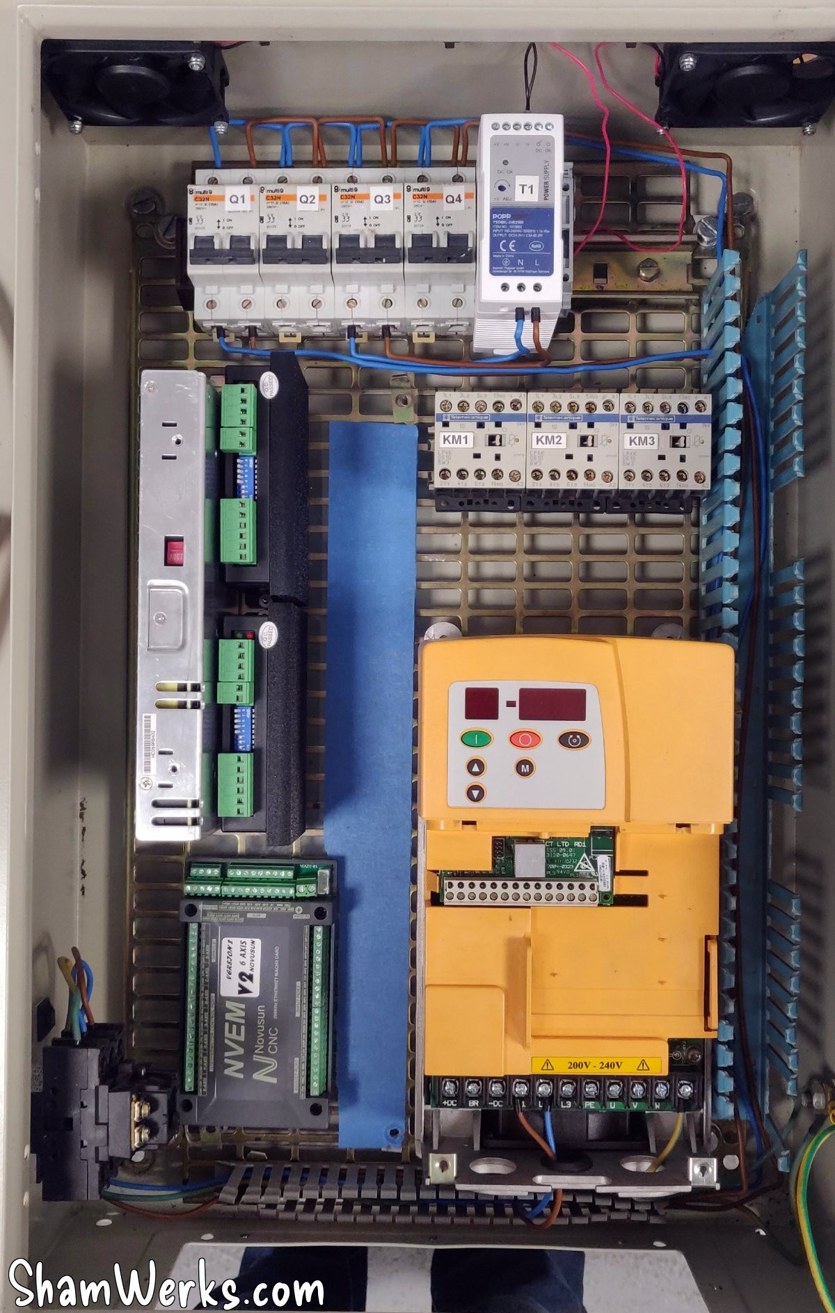
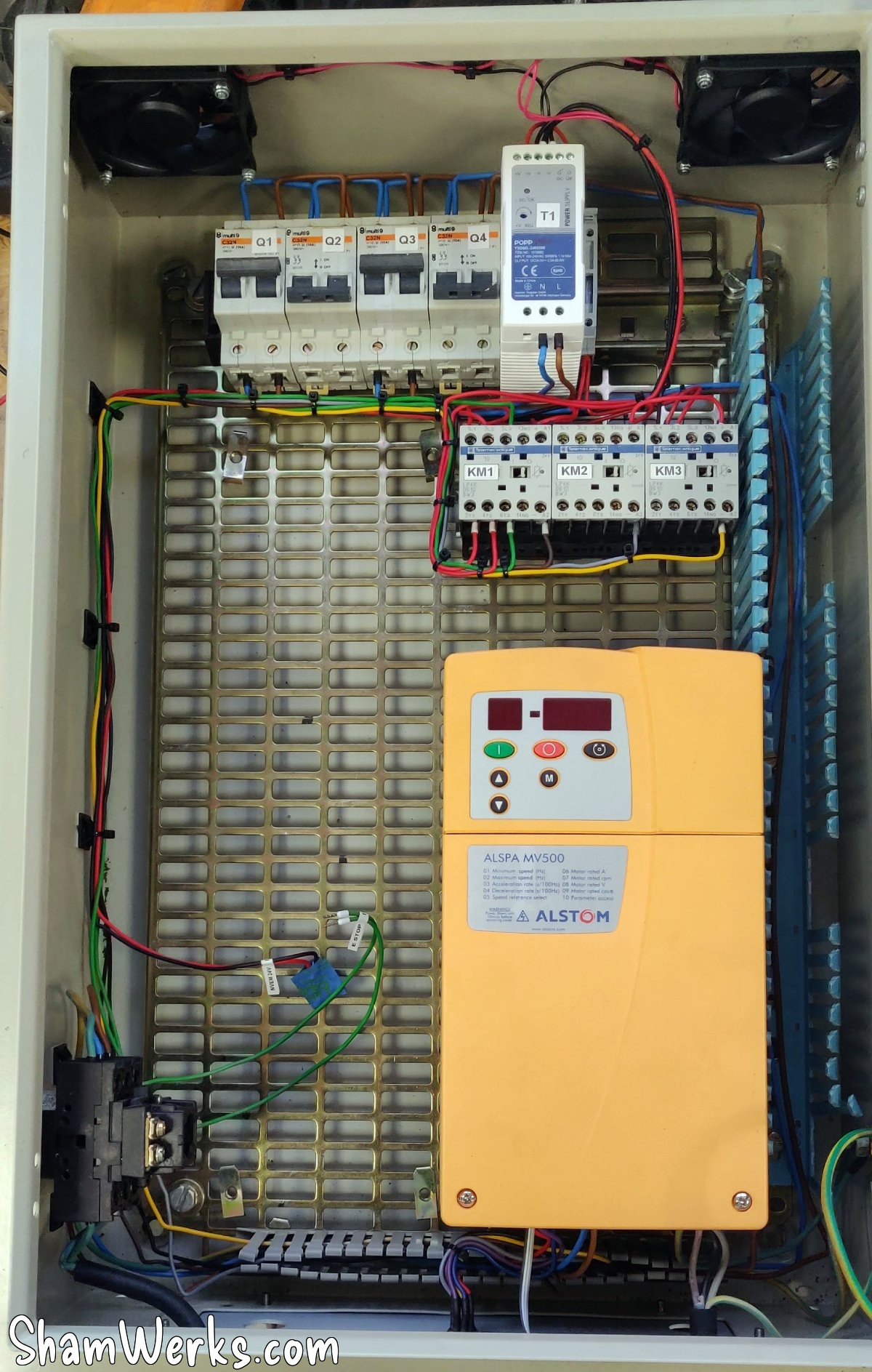
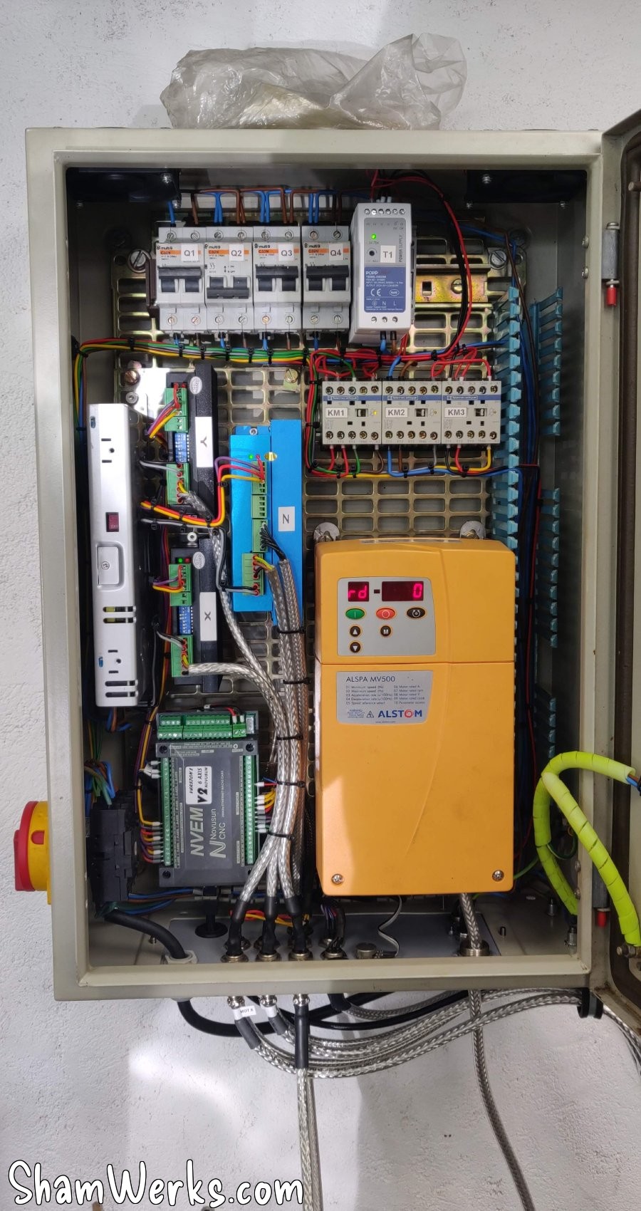
🔧 Wiring
Basically, I have a main disconnect switch, 4 circuit breakers for safety, 3 relays (emergency stop, pump, lamp), a 24V transformer to power the relay/lamp/fans/CNC controller, and a 48V transformer for the stepper motor drivers.
Now all that remains is to wire it all up! If you do it step by step, marking each wire on the diagram, paying attention to where the cables go, it's not very difficult, but it's quite time consuming! All my wires have a small crimped termination on the end, this prevents the strands from being crushed - and it's cleaner.
I know it's not ideal to have the frequency inverter in the same cabinet as the CNC part, due to the risk of interferences... To limit the risk I took care with the grounding, tried as much as possible to separate the control/signal wires from the power wires, and used shielded cable where I feared interference.
Besides, I had been optimistic and I had first powered the motor via an unshielded cable (having only that on hand at that time)... Bad choice, each time I started the PC screen went off (thanks to the interference generated by the three-phase inverter), it's a shame on a CNC machine controlled by the PC. 😁
So I revised the copy, 4x1.5mm² shielded cable, mounted on cable glands with shielding on the cabinet side and the motor side. And no more problems after that!😉
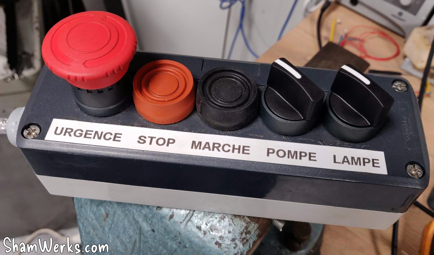
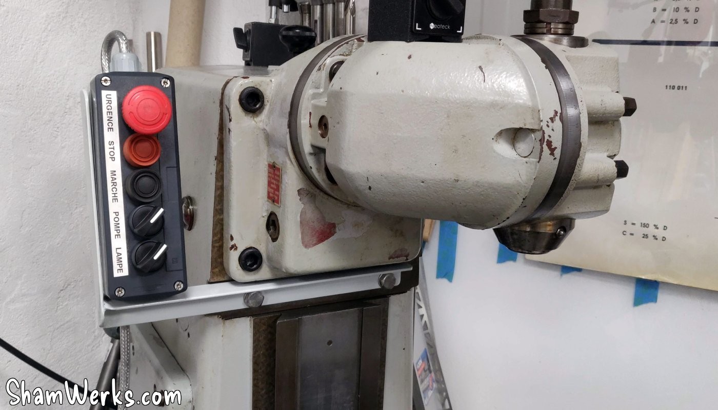
🔧 Remote control box
I'm using a Schneider Harmony control box, simply because I got it second-hand for cheap. It's a nice looking thing and easy to wire/debug, with the contacts mounted at the bottom of the enclosure, and the button heads coming from above.
The box is connected to the cabinet via a 7-wire shielded cable, and an 8-pin aviation connector.
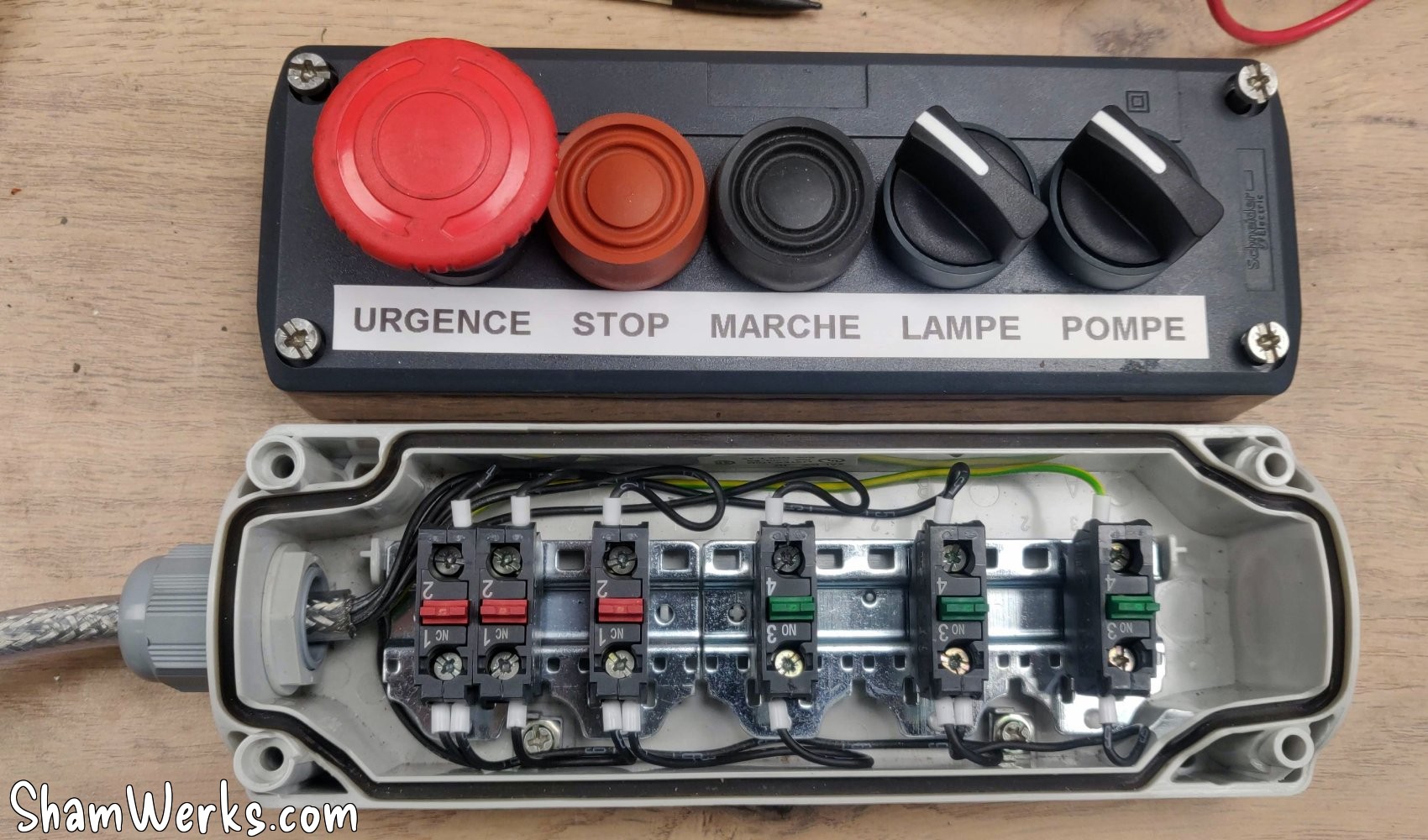
Unfortunately, the CNC controller does not support the "instant contact" mode (instant pressure / latching) to control the VDF. I have in mind a small electronic circuit to allow the instant start/stop buttons of the remote box to work as they are supposed to, in parallel with the CNC controller. But that will be for later!
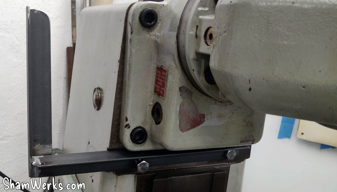
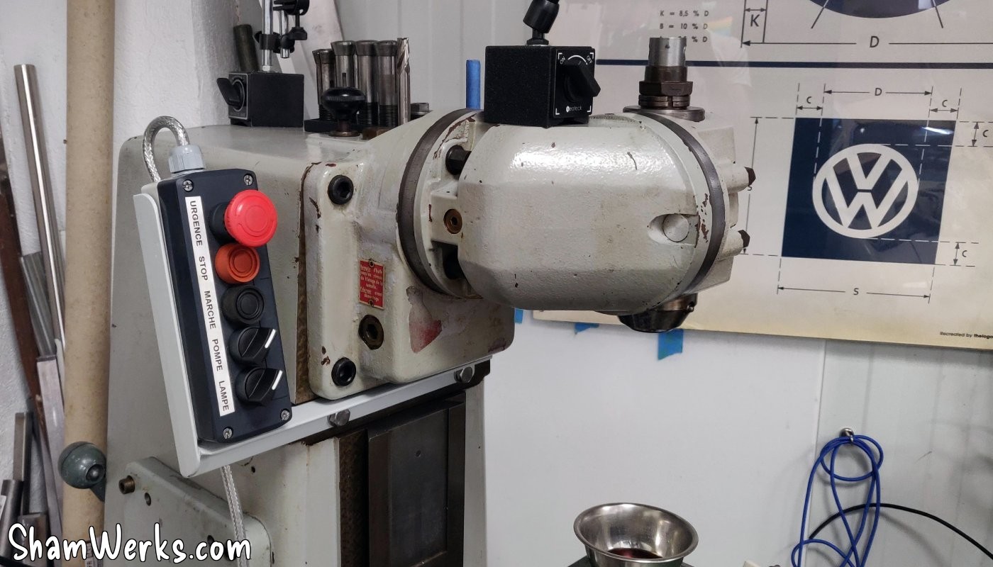
I also made a welded support that attaches to the milling machine, so that the controls are easily accessible (especially the emergency stop!). Two pieces of welded angle iron, a few holes, two coats of paint, and voila:
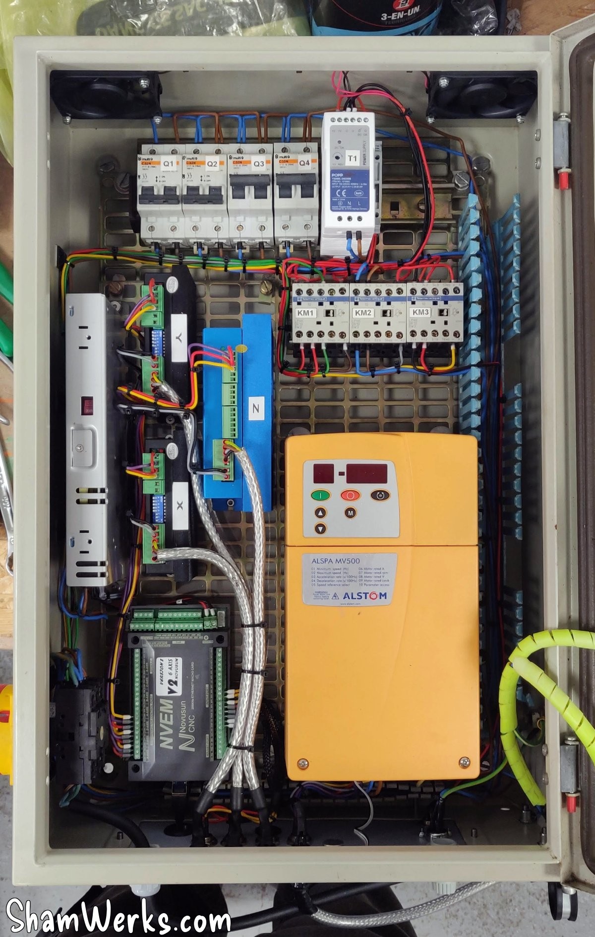
🔧 CNC
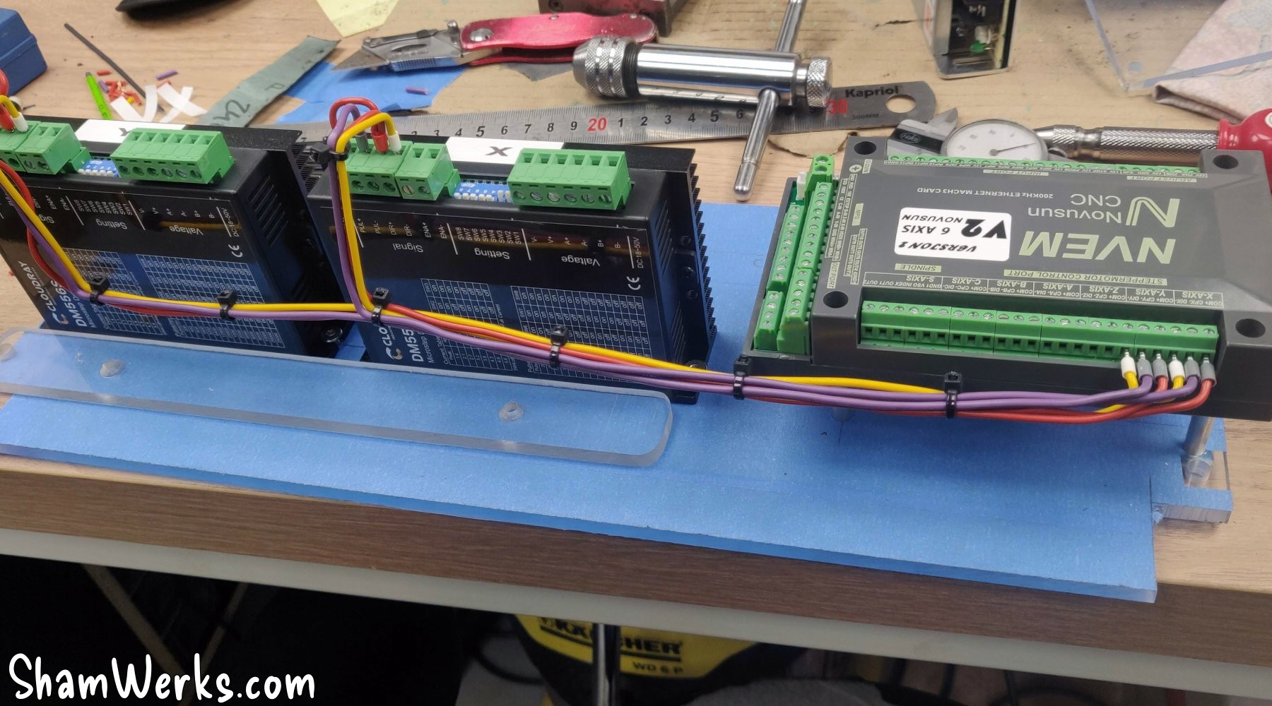
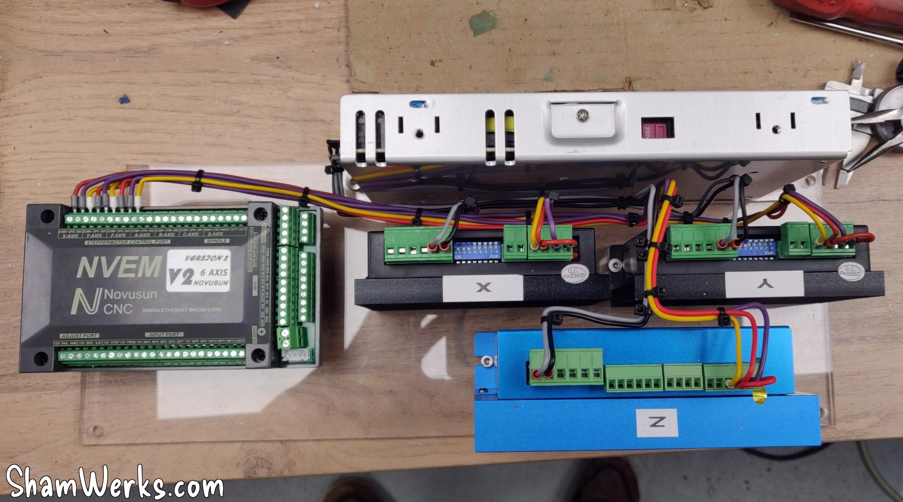
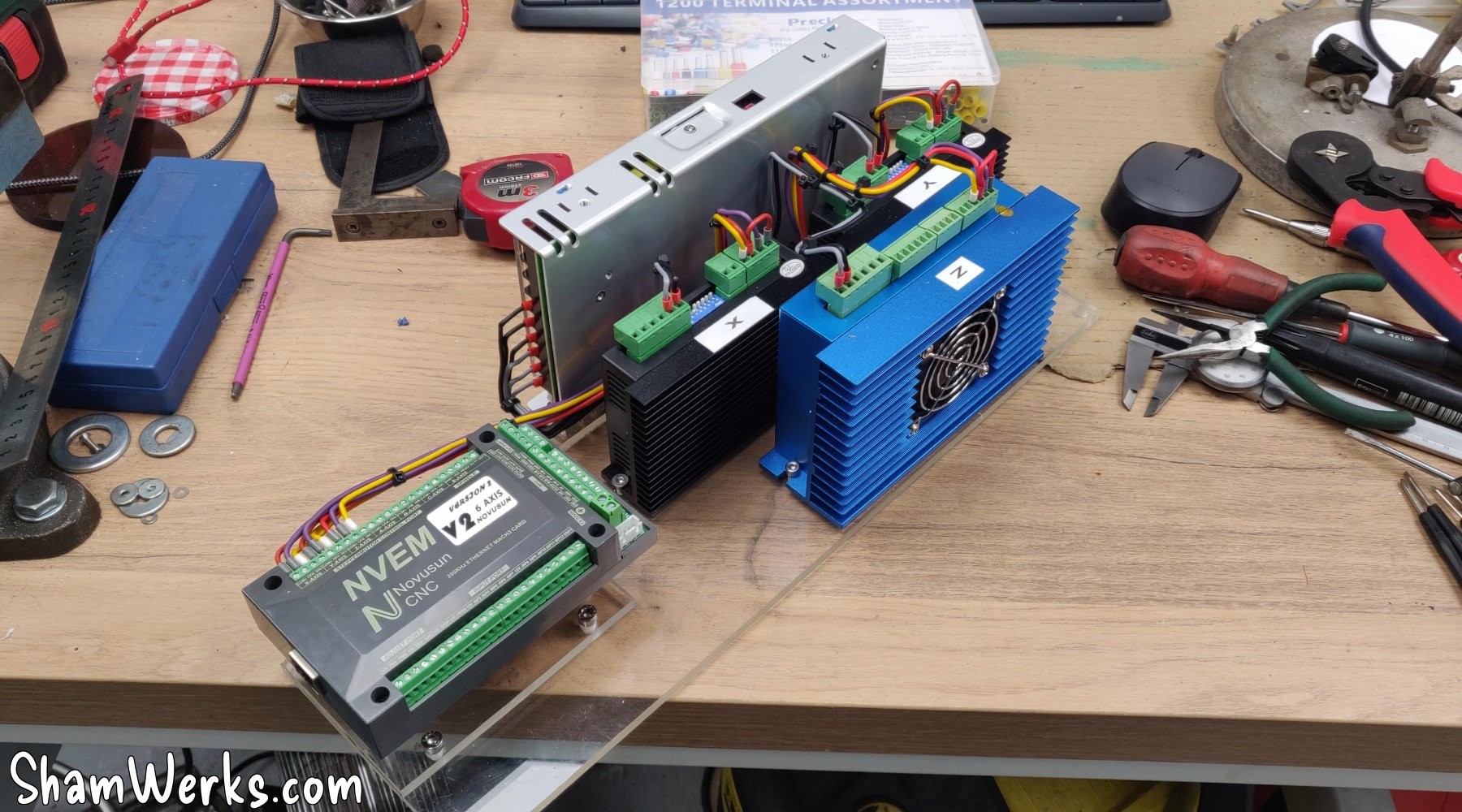
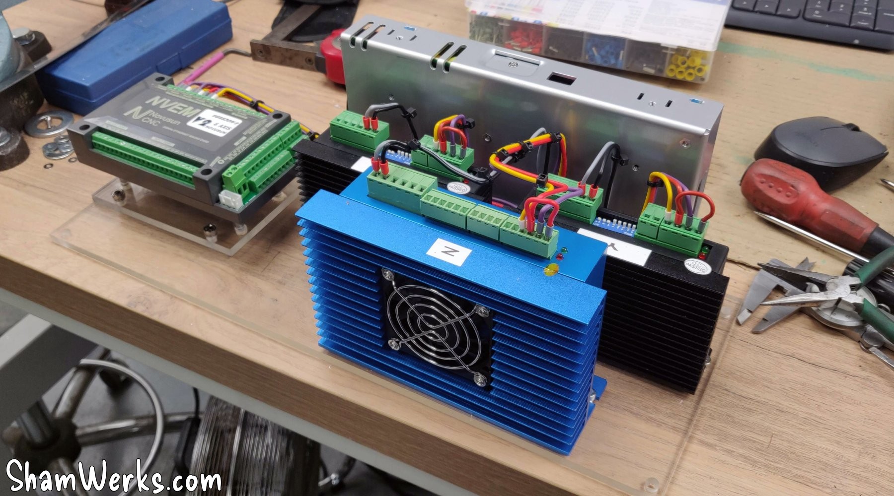
The CNC part (controller, 48V power supply, stepper drivers) is placed on a piece of scrap plexiglass. This allows me to wire everything comfortably, with better accessibility, rather than directly in the cabinet. Once everything is wired, the whole thing is fixed in the cabinet.
The controller is a NVEM Novosun V2, connected via Ethernet to the PC. I bought this because it was on sale (cheap), and it is a very commonly used controller... But if I had to do it again, I would go for another platform, the NVEM being not easy to integrate, and it has some potential bugs.
Normally screwed from below, I fix the NVEM on a small added plate, itself screwed onto the main plexiglass support plate. This will allow me to remove it more easily if necessary, without having to disassemble everything. I add small custom spacers to align its Ethernet jack with the hole under the cabinet - we're not savages.
Same treatment for the 48V power supply for the stepper motors, which is also fixed from underneath, so I put it on a separate plate.
I struggled for a while to get the NVEM controller to start the VDF; in the end, the solution was to insert a small 817 optocoupler module, and it works perfectly. I fixed it neatly into the VDF itself, and now it works like a charm!
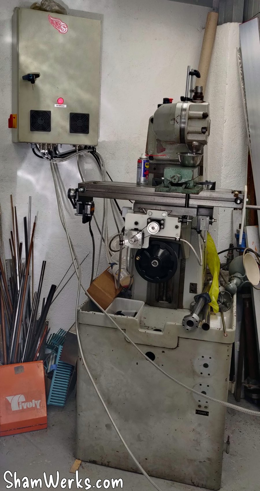
🔧 Result
The cabinet sits on the wall just behind the milling machine, secured via two M10 threaded rods (chemical wall anchors)... Perhaps overkill, but the thing weighs more than 20 kilos in the end, I didn't want it to drop on my foot. 😉
Y-axis motorization
I owe a huge thank you to aSa (who also happens to be my unofficial proofreader) for entrusting me with the safekeeping of his CR-10 3D printer! This allowed me to easily make prototypes of adapters and circuit boards – and since I'm a beginner, I made quite a few before finding the right compromises!
Okay, I had to learn Fusion360 and Cura, and set up a small OctoPrint server on a Raspberry Pi, but it was worth it! 😁

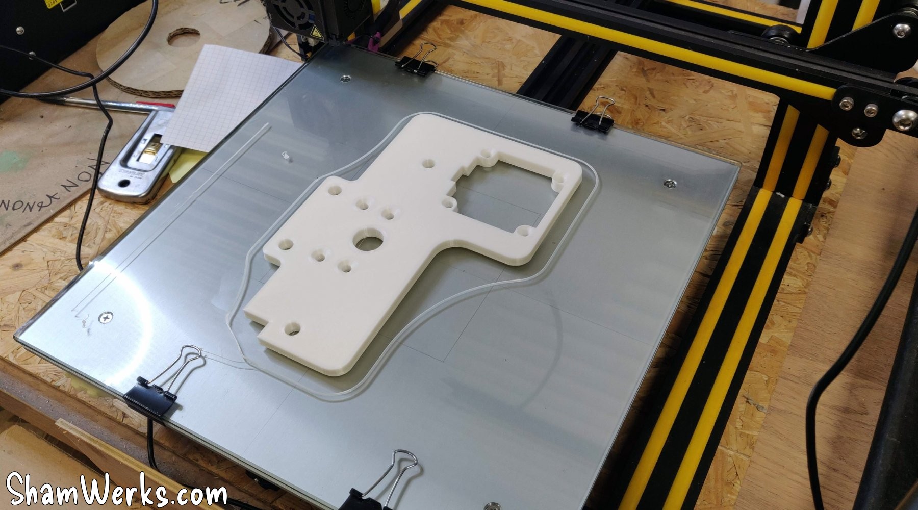
So I'm starting with the Y-axis, installing a 16x300mm ball screw with a 5mm pitch, purchased from AliExpress. The ball screw has the advantage of limiting backlash while reducing friction.
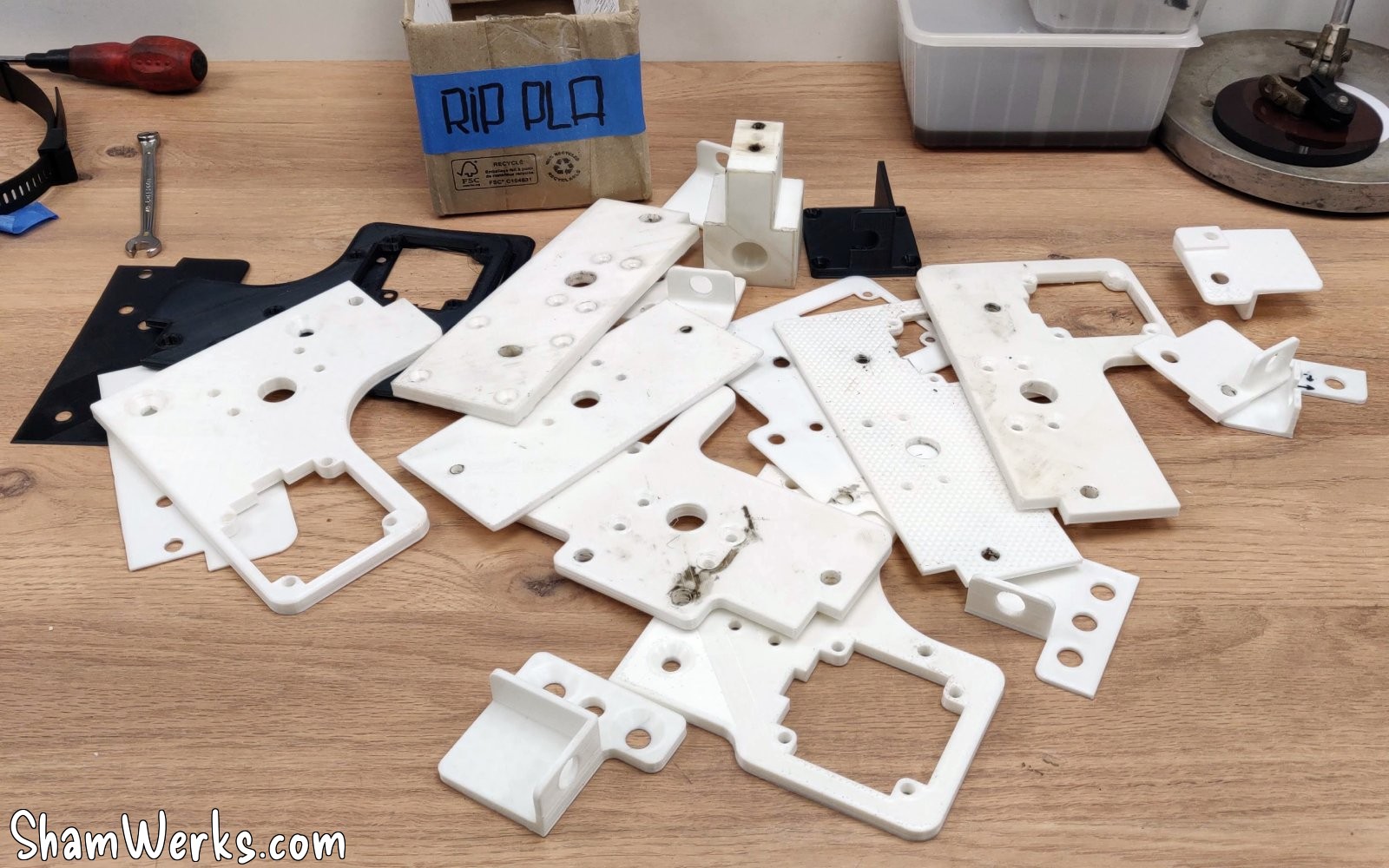
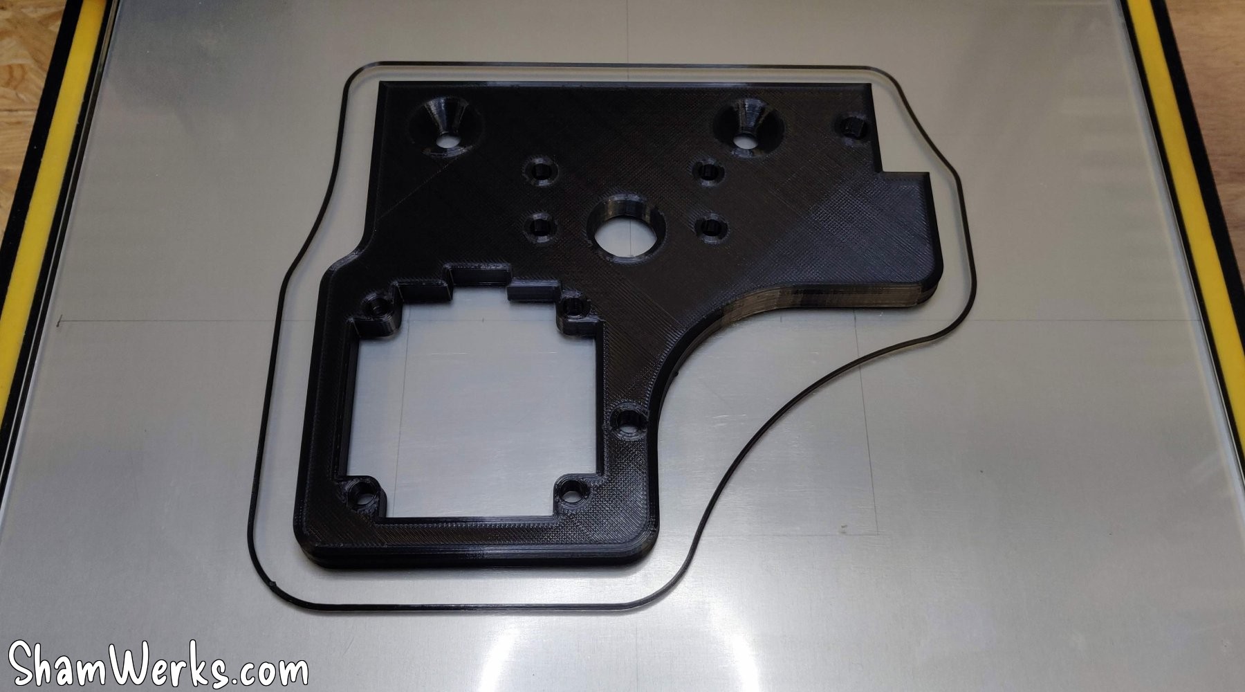
To do this, I need to make an adapter that attaches under the cross slide. I'm making a 3D printed prototype in PLA to validate the approach, which I will then machine in aluminum (PLA being strong enough to allow this machining).
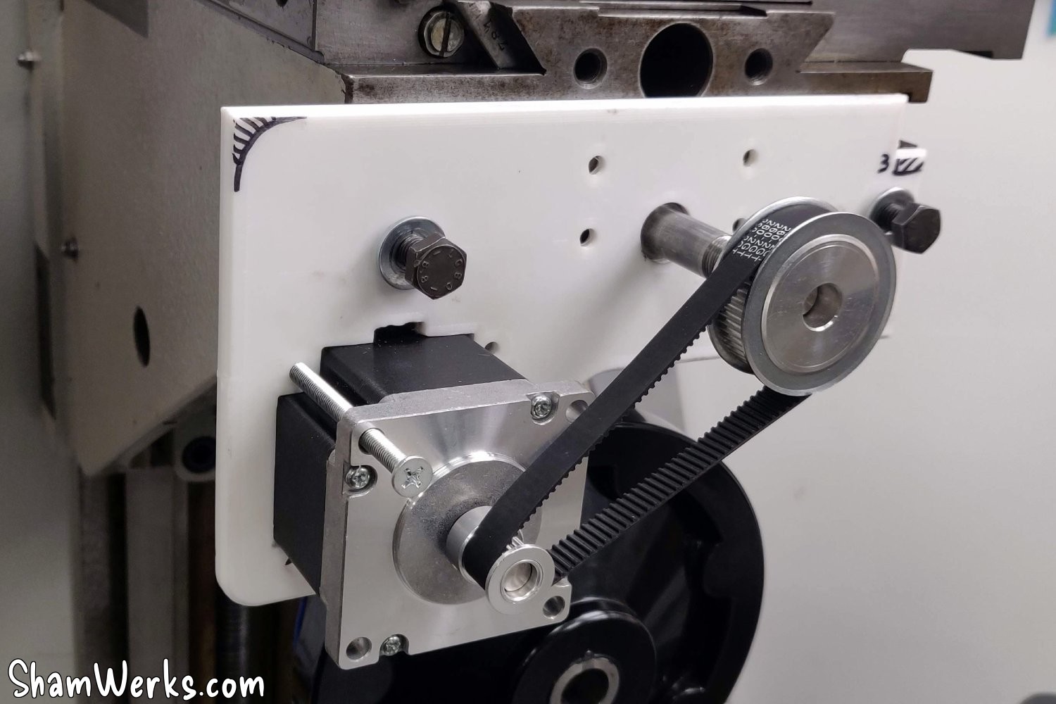
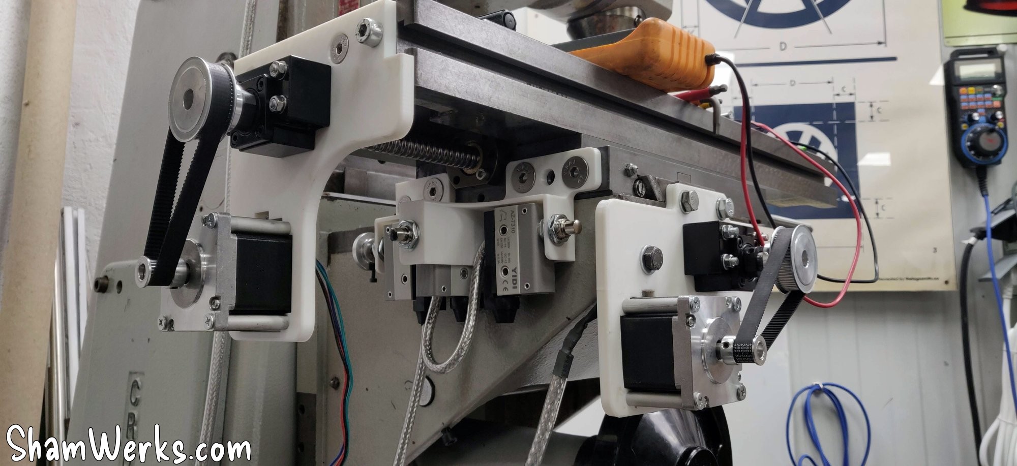
For the motor plates, I wanted a belt drive to double the motor's torque (at the expense of speed, but the moving parts are heavy!), and also to save space. The simplest solution would have been to mount the motor directly on the ball screw shaft, but that would have increased the machine's footprint by a good 15cm, which wasn't ideal. I tried to position the motor at just the right distance to ensure the belt was taut, but it proved difficult in practice (variations in manufacturing, slack, etc.). I'll revise my design to find a way to tension the belt.
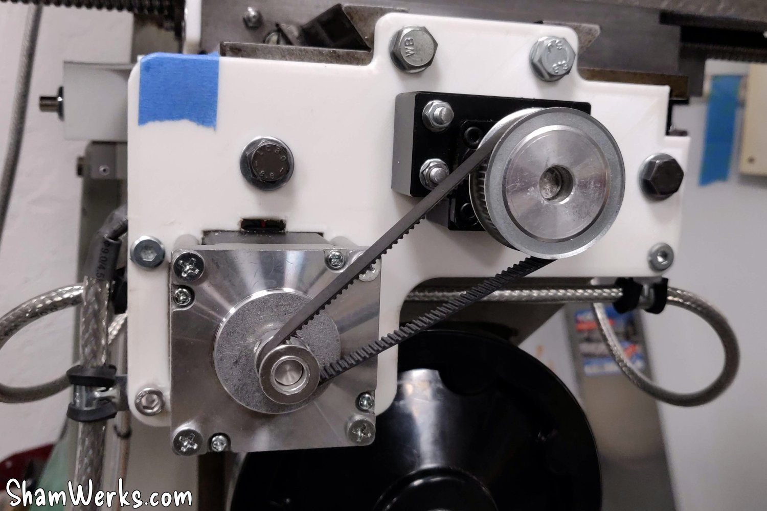
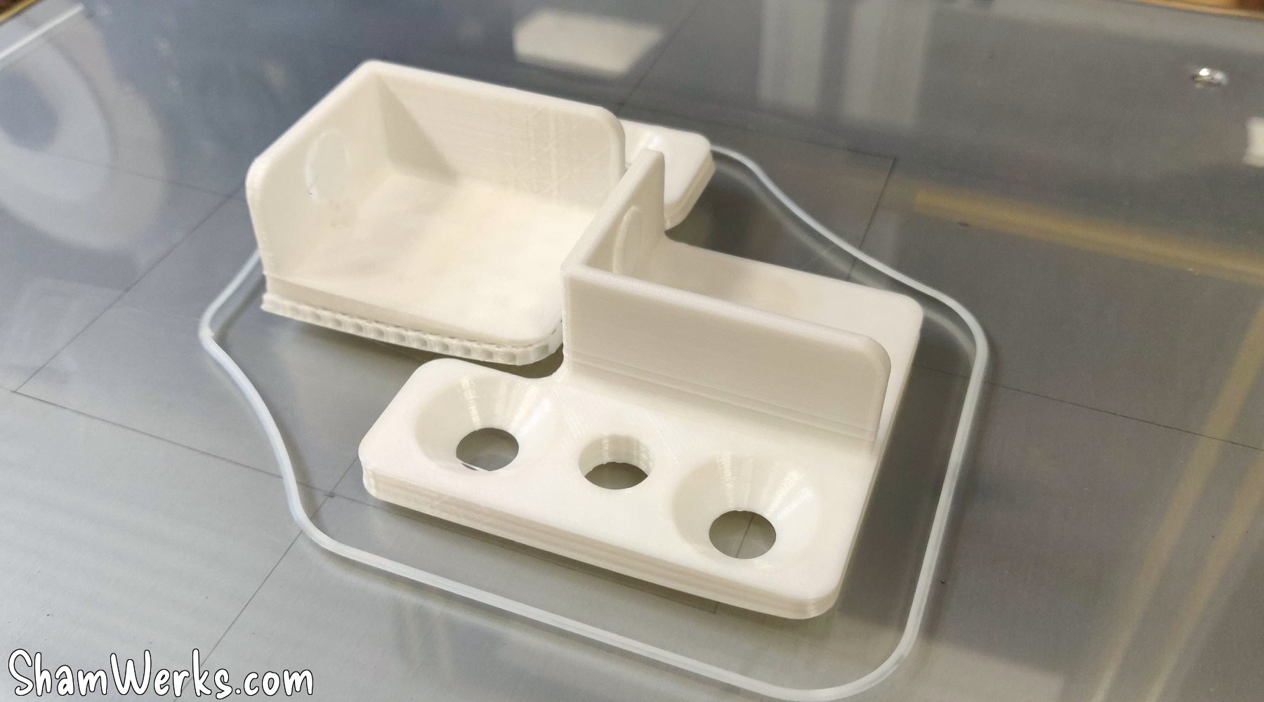
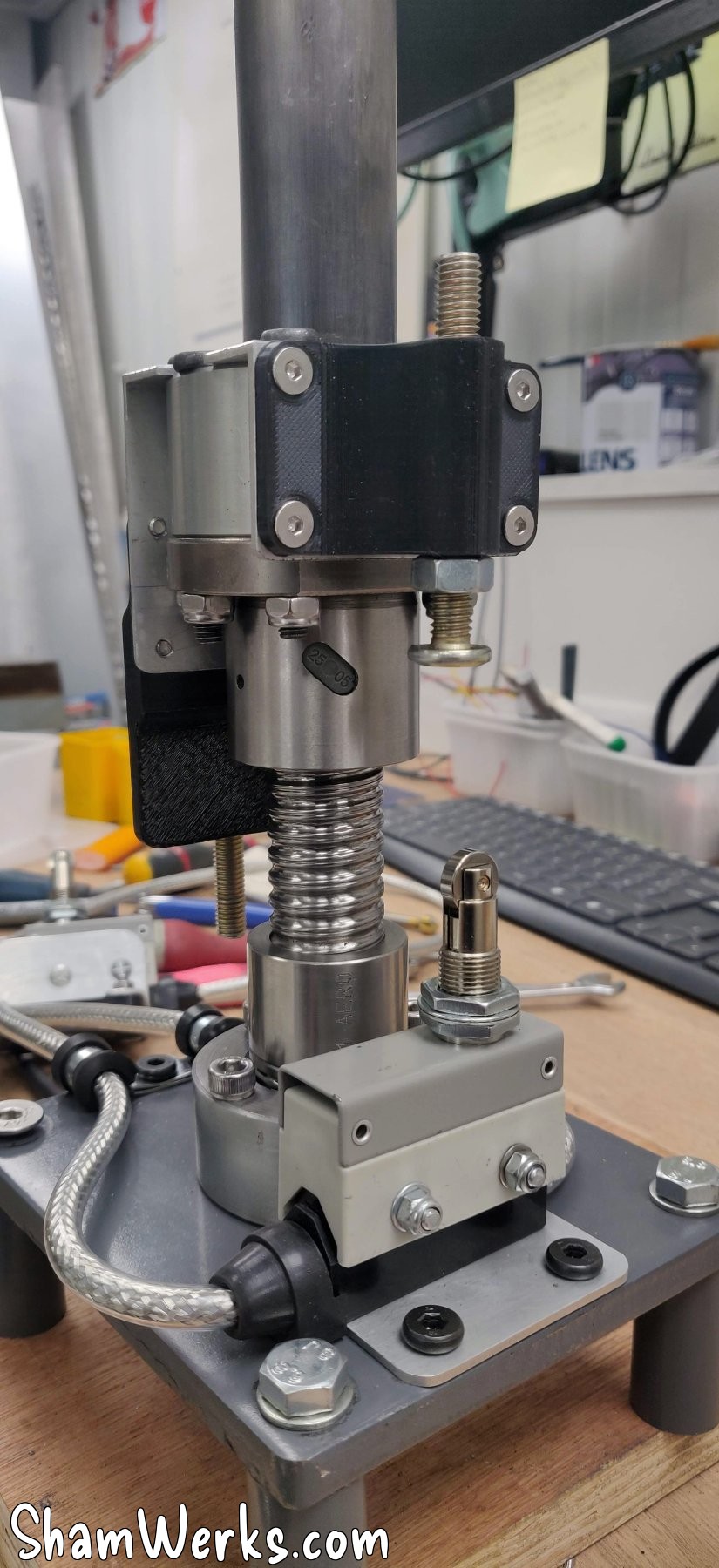
Just like the circuit boards, I 3D print supports for the limit switches, for a clean and compact assembly. The limit switches are wired in series with shielded wire, again to avoid interference.
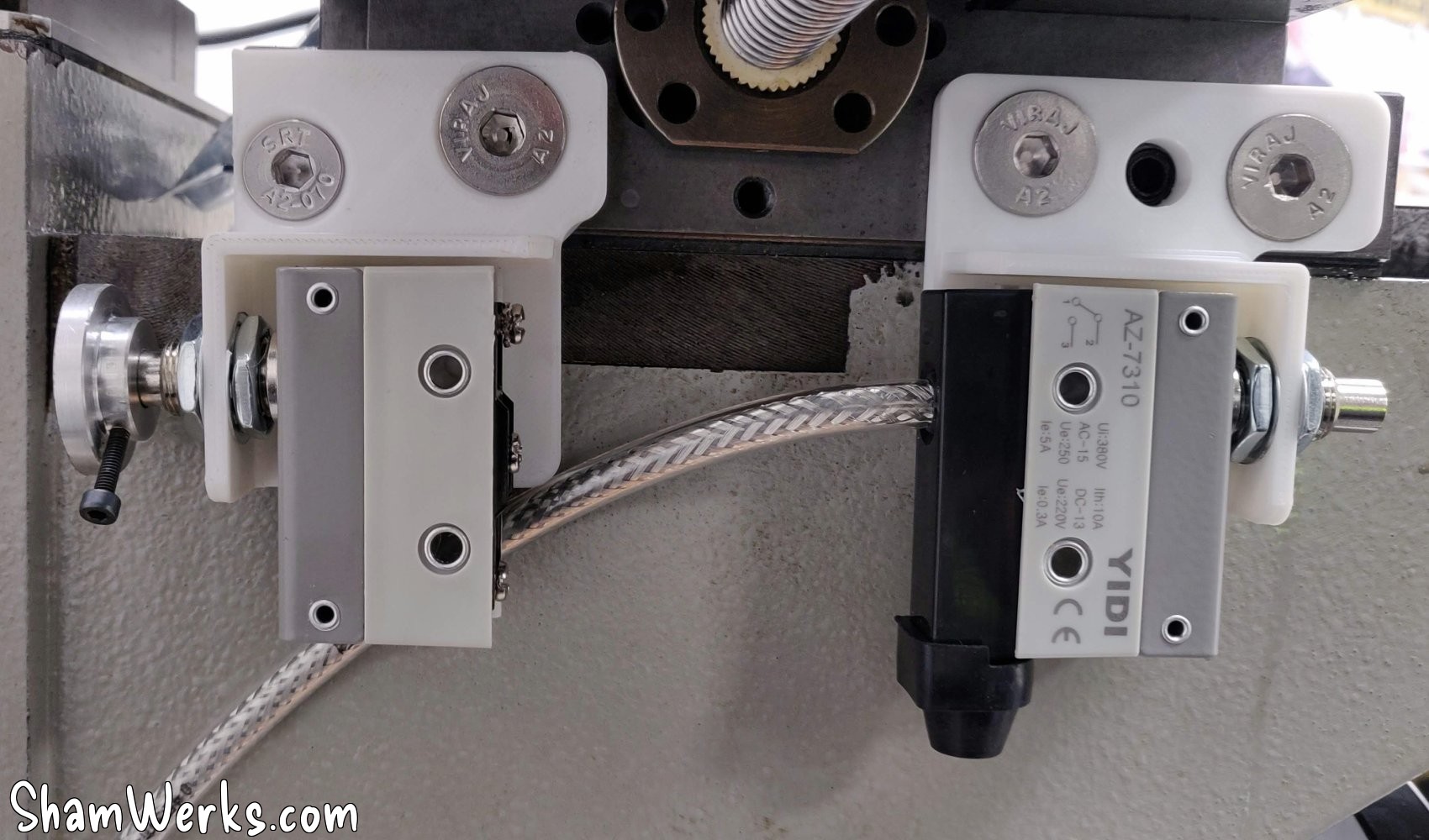
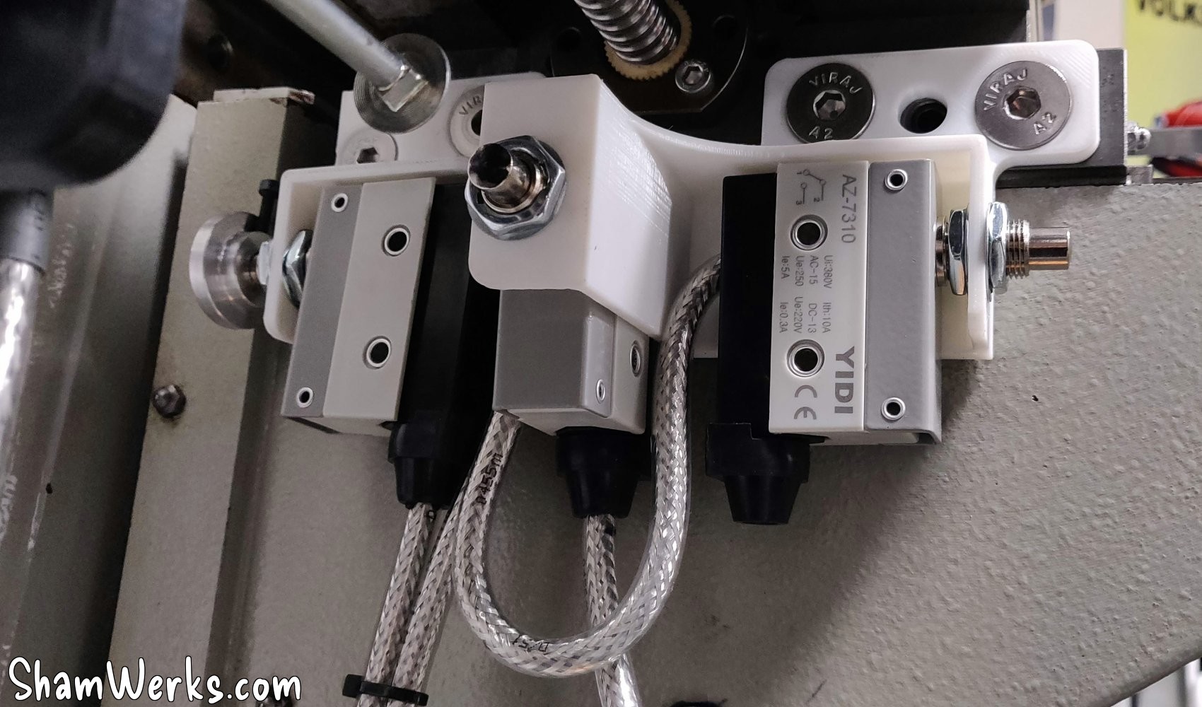
The PLA motor mounts will obviously need to be remade in metal later, but they allow us to validate the assembly for now. The limit switch supports will remain in PLA.
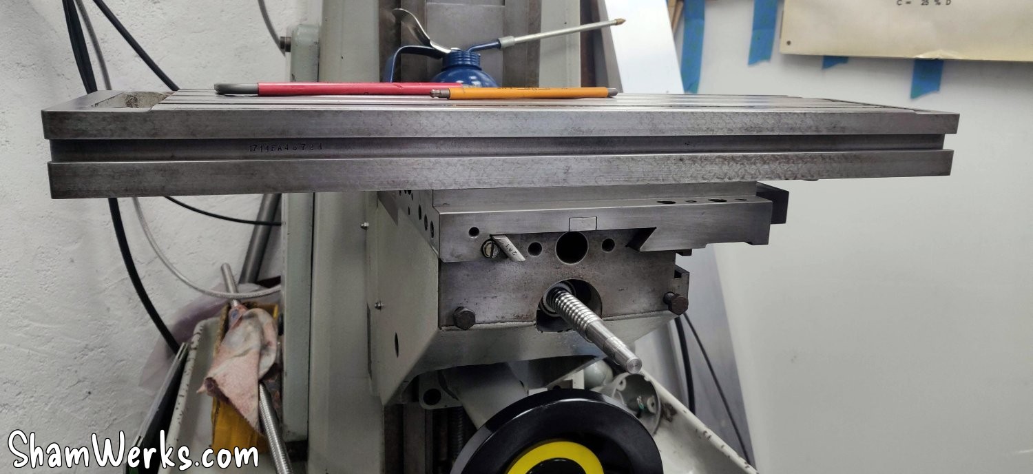
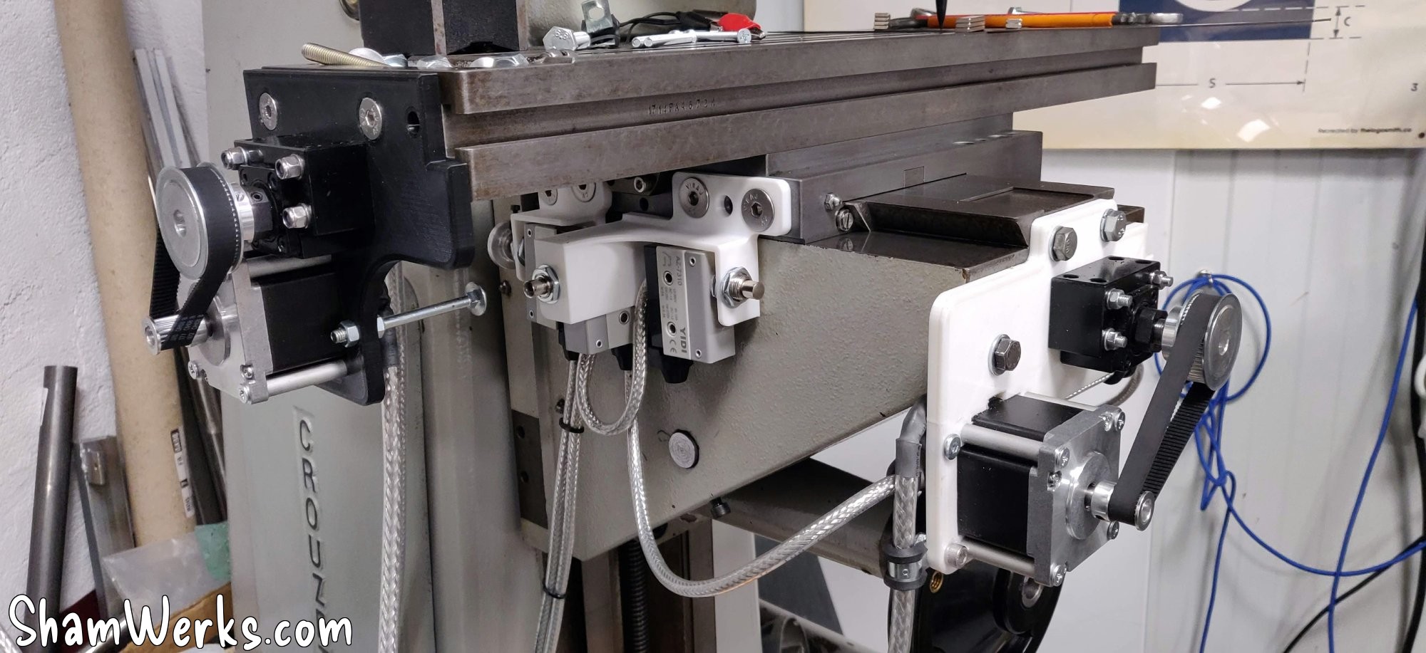
X-axis motorization
The axis will be driven by a ball screw diam 16mm/length 800mm, intentionally too long, I' wi'll cut it to final length when I have finalized my assembly.
And then, we got incredibly lucky: the ball screw nut fit perfectly into the cross slide, a tight fit. Couldn't have done any better if I'd wanted to. That was a nice surprise! 😮
I drill 4 holes in the carriage to fix the nut, and there you go.
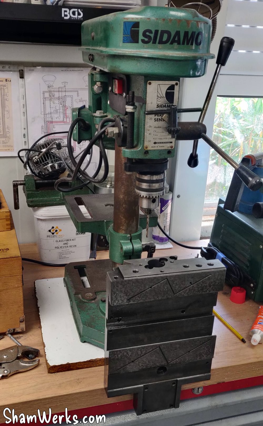
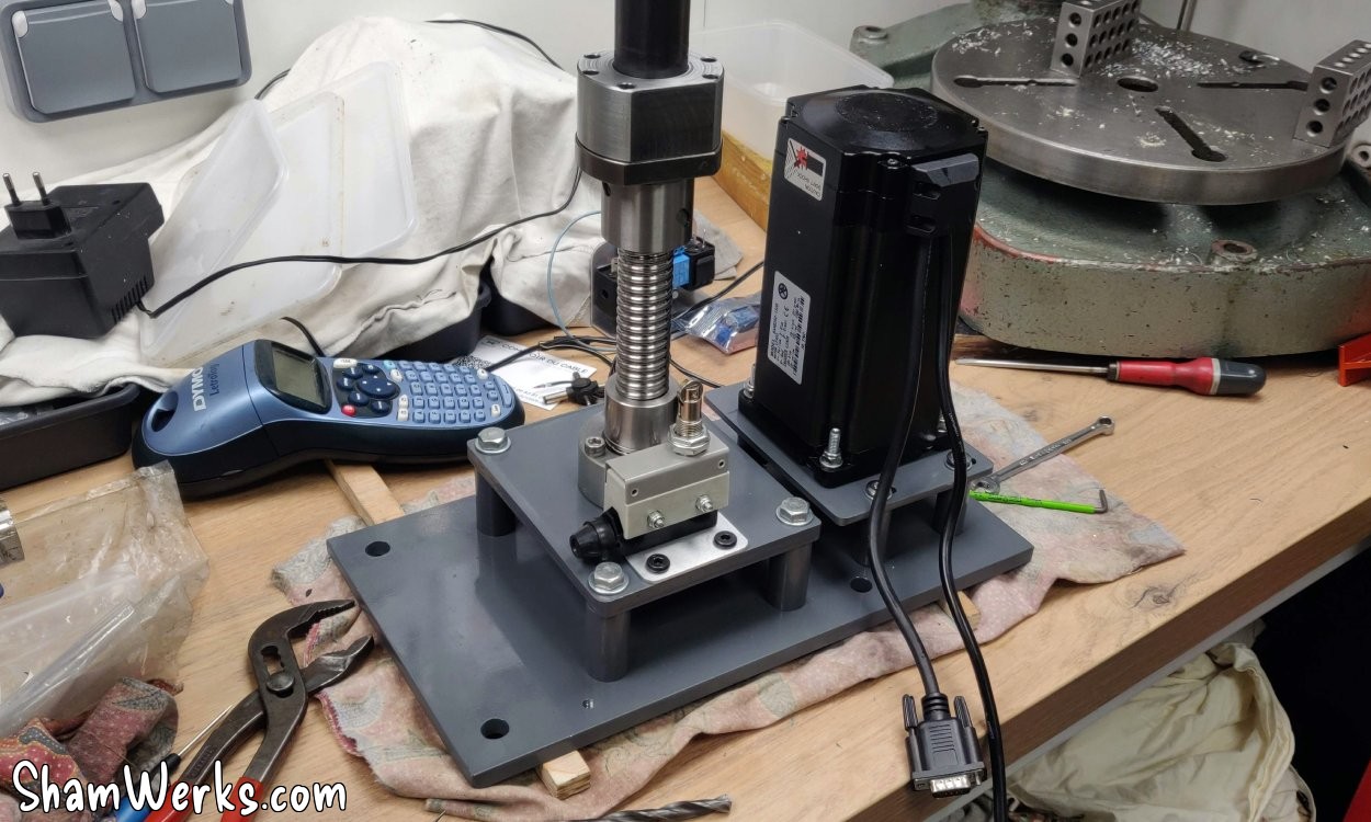
Well, the drilling itself was a bit of a makeshift affair; my drill press wasn't tall enough, so I had to improvise...
A bit borderline but no need for insane precision: 4 holes at 4.2mm, M5 tapping, and it's mounted.
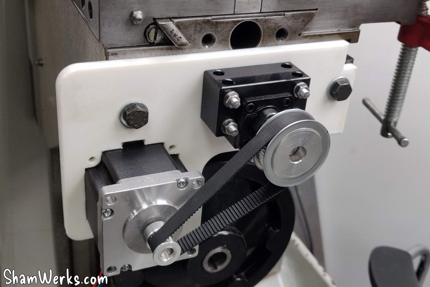
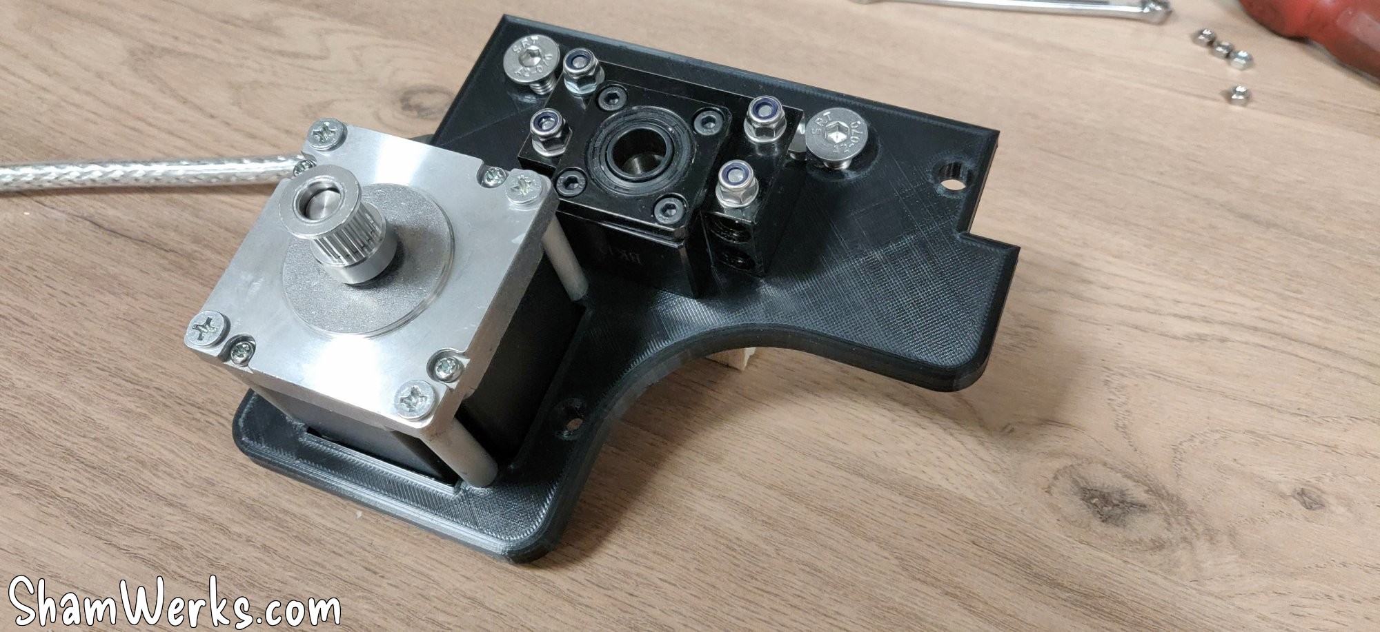
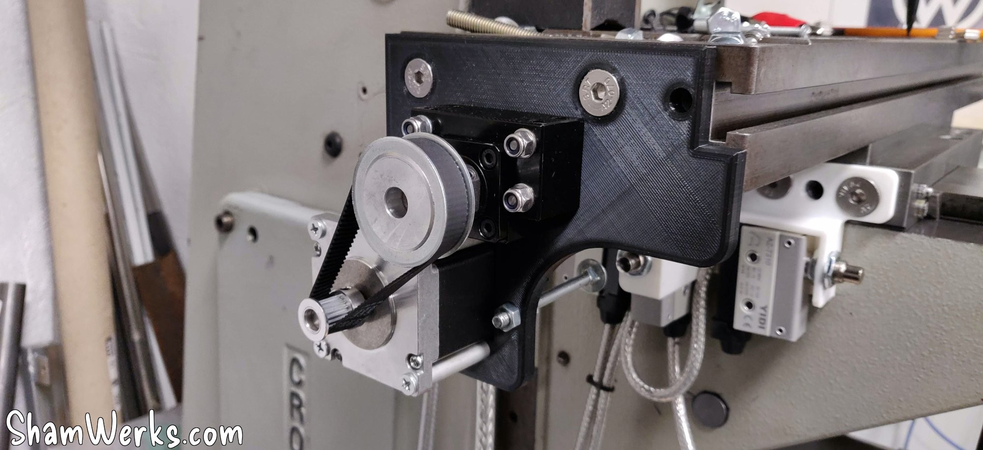
I then moved on to the motor adapter plate. I wasn't happy with the first version; the motor was too far from the screw (even though I had calculated everything), so I revised my design with a shorter belt...
Much better, but I still have this belt tension problem; I will need to make yet another new version of the assembly to be able to adjust the tension.
Z-axis motorization
Initially, I wanted to make the X/Y plates out of aluminum first to stiffen/finish them, but manually raising and lowering the Z-axis is a nightmare; I can only move it forward in quarter turns because the crank handle keeps hitting my Y-axis plate... Long story short, I'm finally starting with the Z-axis! 😁
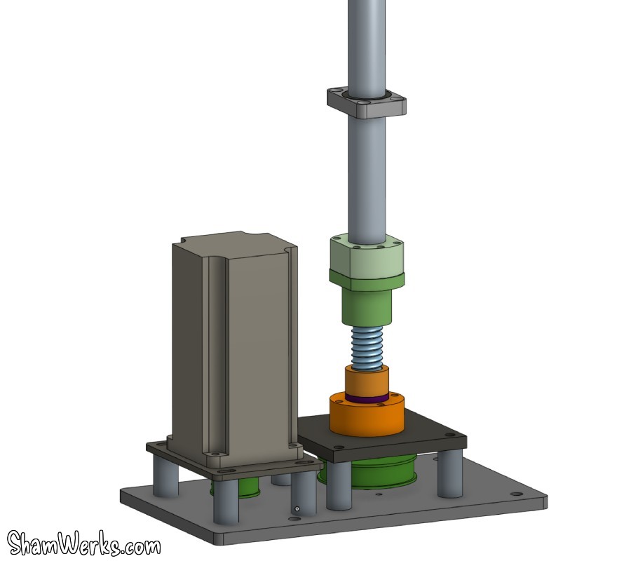
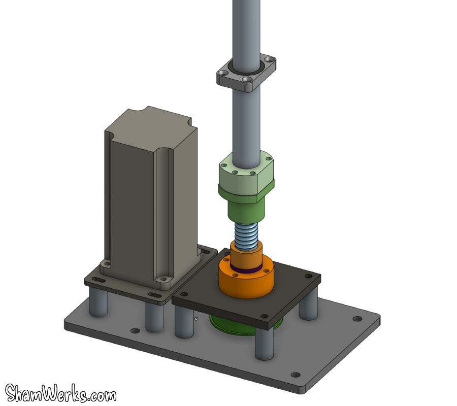
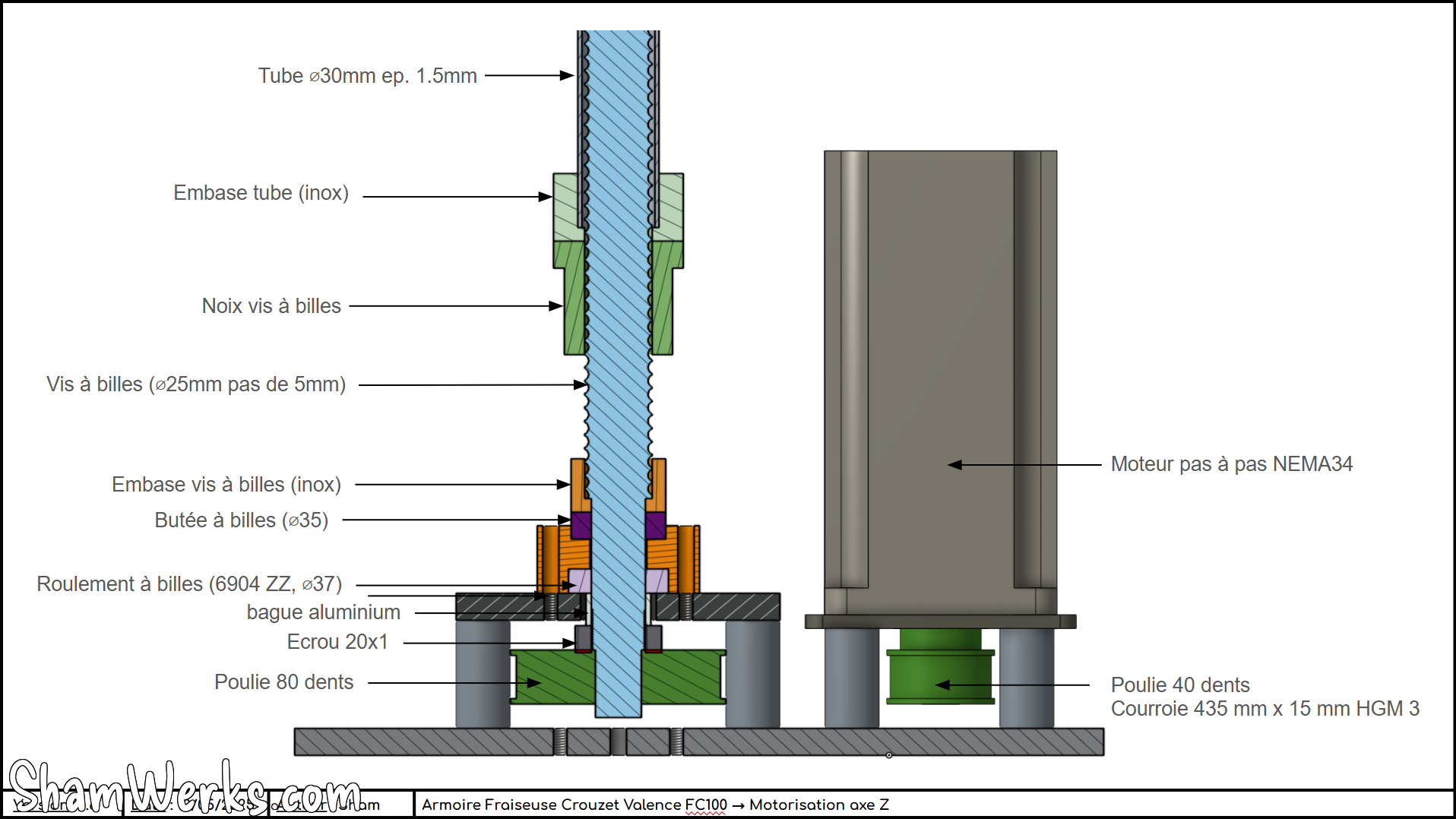
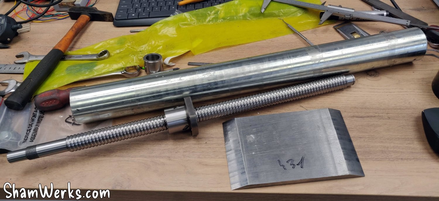
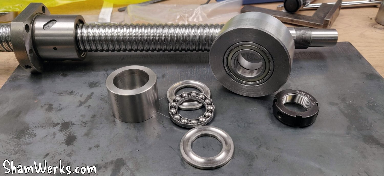
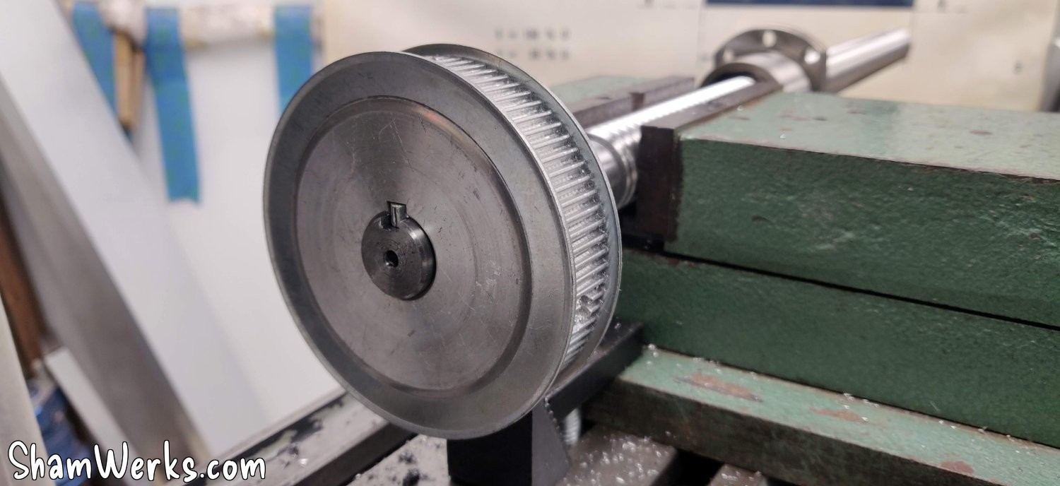
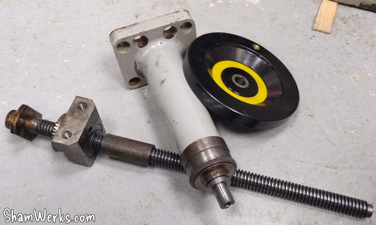
This is the main part of this conversion... I've thought about it for a long time and I have a plan of attack: the movement will be driven by a stepper motor, via a toothed belt drive (15mm wide, 390mm circumference) and a 1/2 reduction (HTD pulleys with a 3mm pitch, 40 teeth and 80 teeth). This drives a ball screw (25mm diameter / 5mm pitch / 550mm length), which rests on the mechanism at the bottom of the milling machine, via a ball thrust bearing (ref. 51104, ID 20mm / OD 35mm / H 10mm) to support the weight, and a 6904ZZ bearing (ID 20mm / OD 37mm) to absorb the lateral forces. This raises and lowers the nut, and I transmit the movement to the machine's table via a tube.
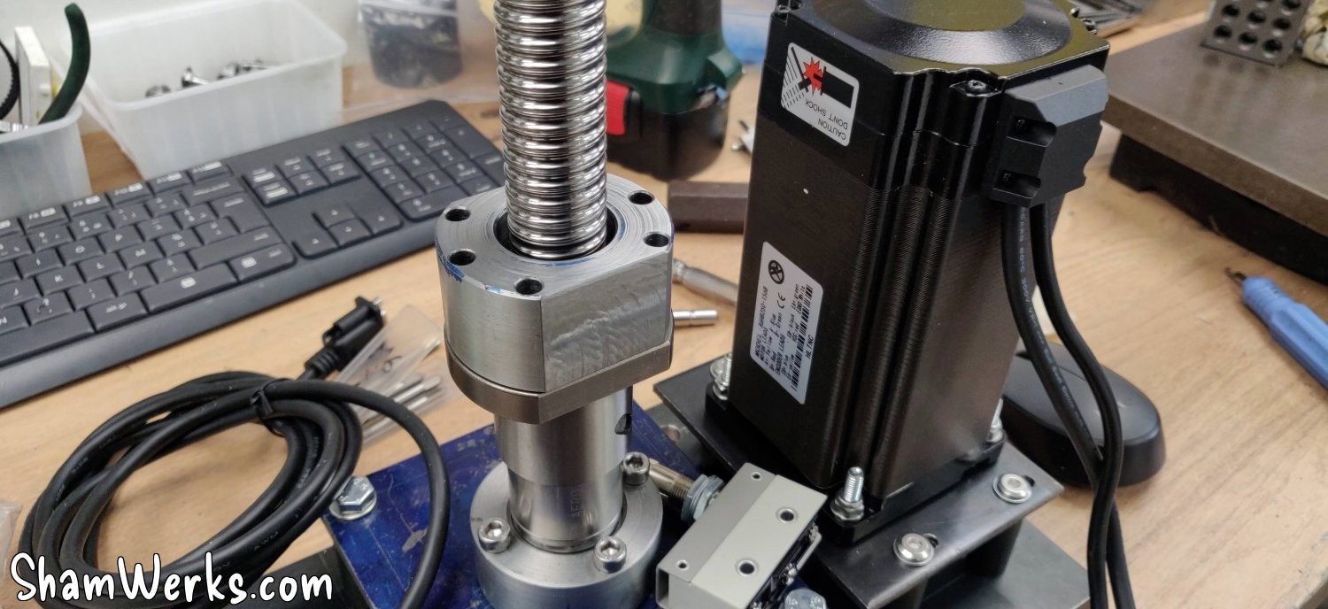
The stepper motor is a Nema 34, 176mm long, 48V, a hefty piece of kit weighing over 5 kilos. It's "closed loop", meaning it has an encoder on the back, and if it misses a step the driver detects and compensates automatically (that's the DB15 connector).
I spent quite a bit of time on OnShape.com (great online tool, 100% recommend it!) to model all of this, here's the result:
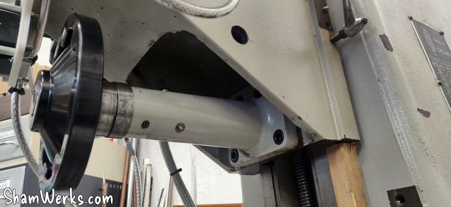
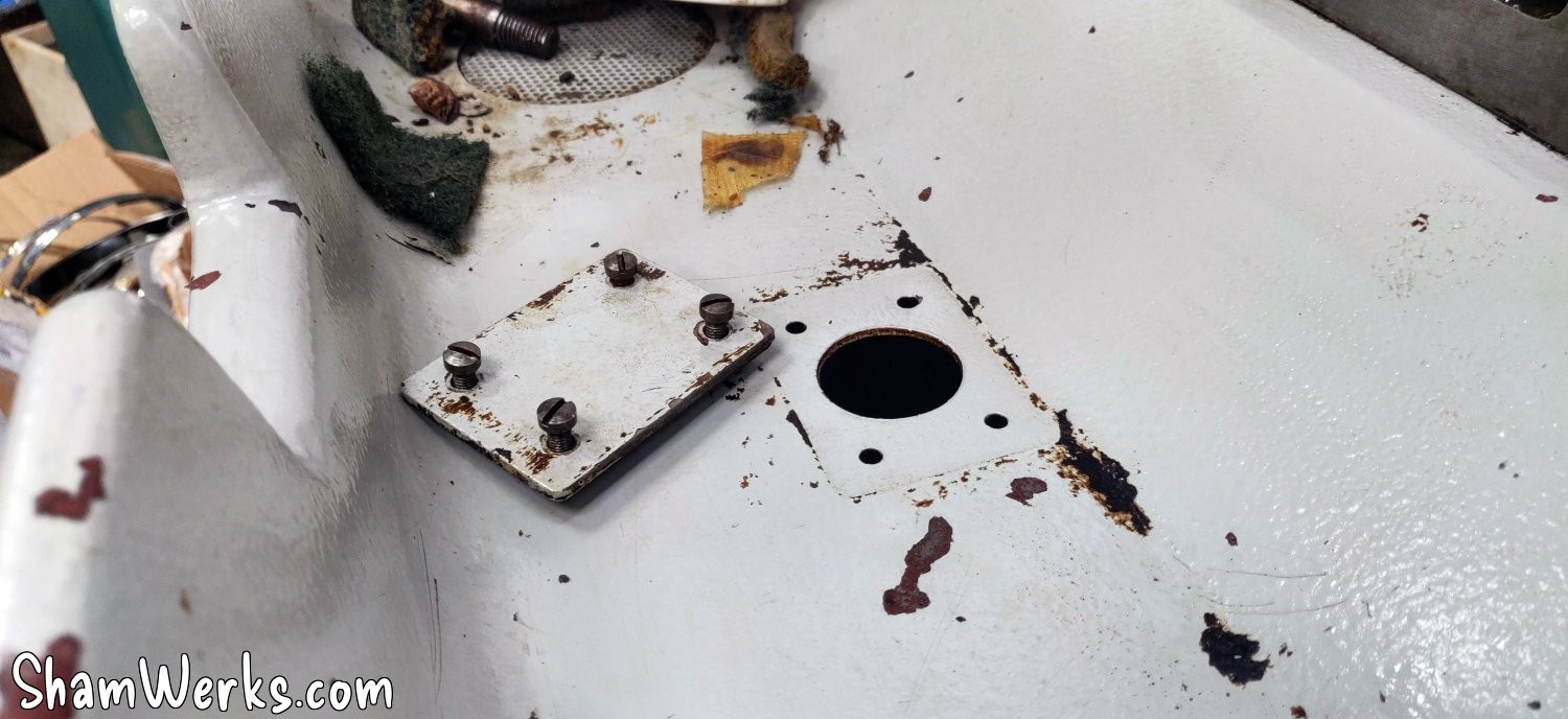
This milling machine was available in versions with automatic cycles, with axes controlled by pneumatic actuators. Consequently, the table console has two bores for a 20mm axis, and at the bottom the support has a hole (plugged on mine by a small plate and 4 screws) for the cylinder to pass through, perfectly in line with the table axis (and at the very bottom in the base, a small 6mm hole indicates the alignment).
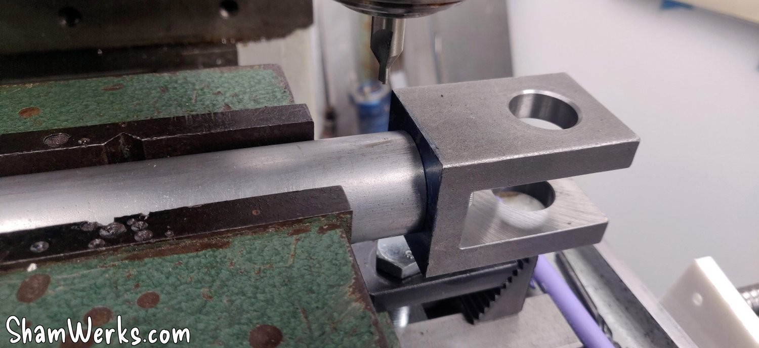
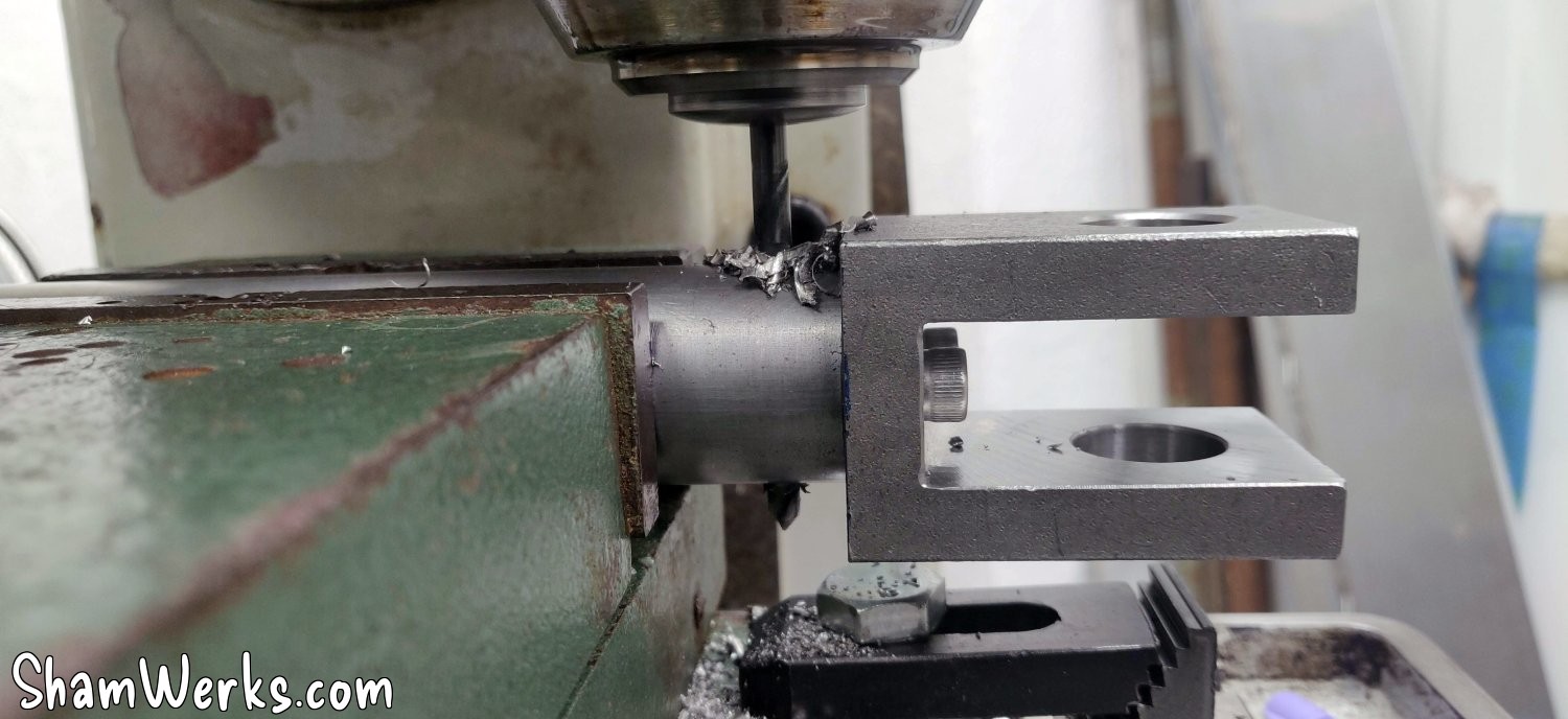
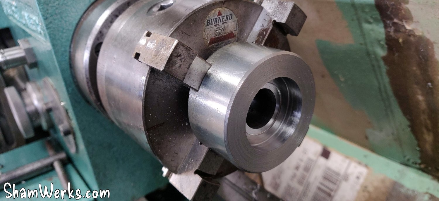
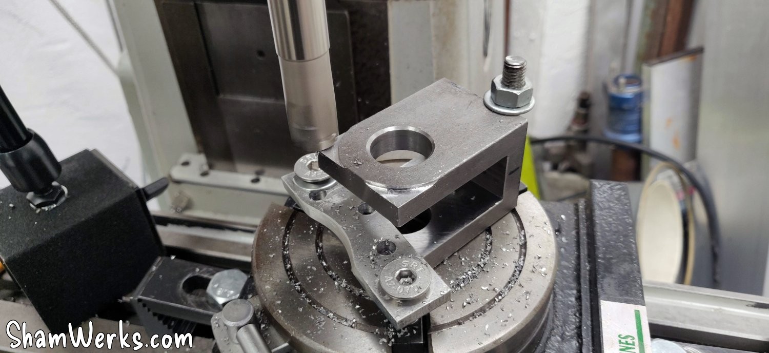
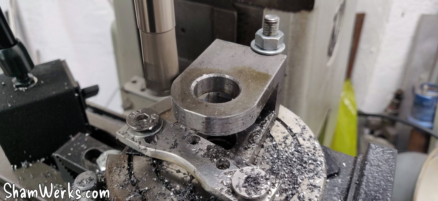
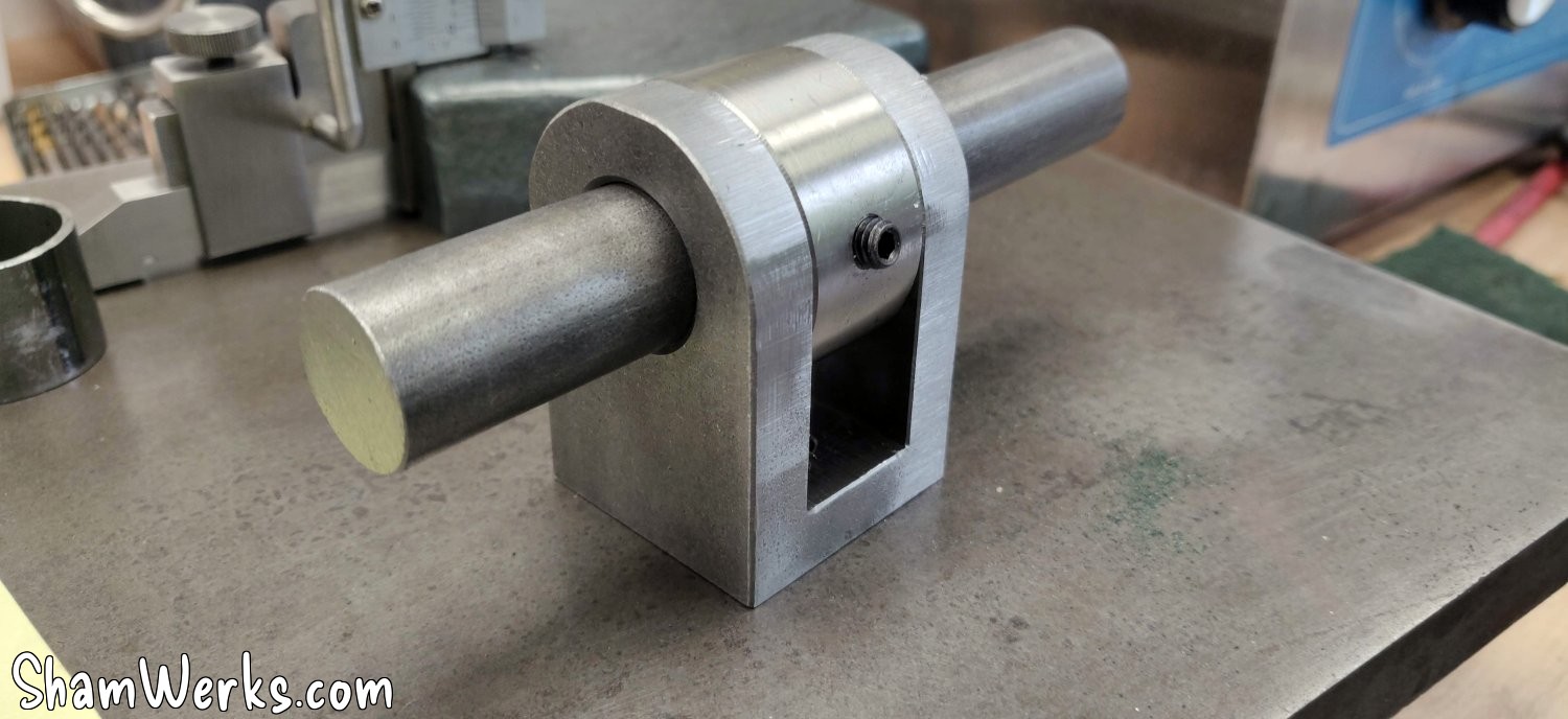
So at the top it's easy, a 20mm steel shaft, a clevis for a cylinder in the middle (I could have machined it myself, but at €14 on ManoMano, it's not worth the cost of the material + the time spent), and a large ring machined on a metal lathe with a BTR screw to laterally clamp the clevis on the shaft.
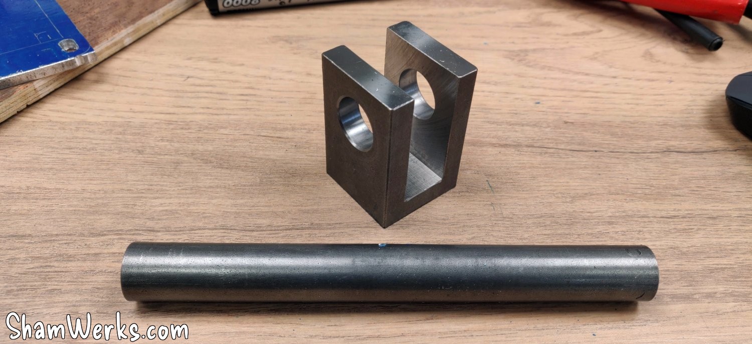
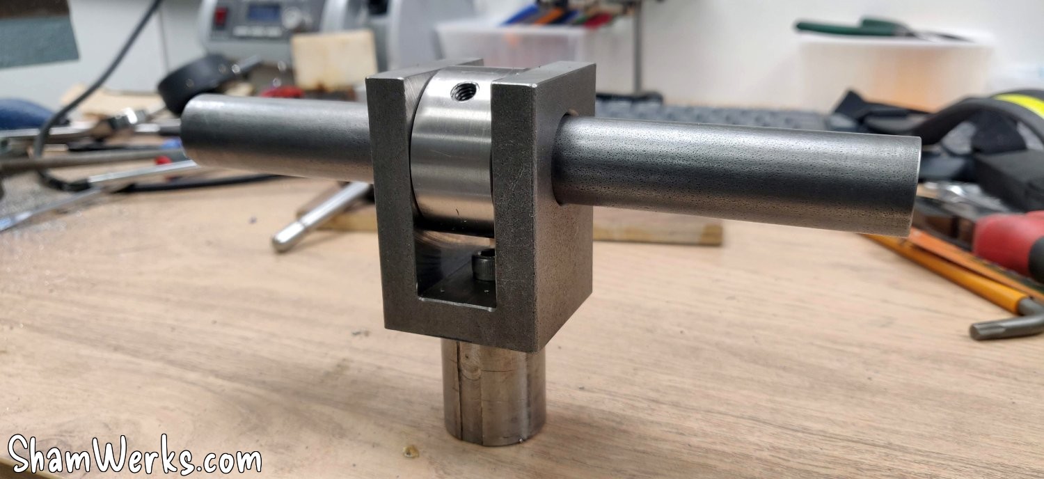
The yoke is fixed with two Allen screws to a small stainless steel round bar that I machined on a lathe, which is then fixed inside the steel tube (30mm outer diameter, 1.5mm thick) that transmits the movement. I left several taps and a center drill bit on the workbench, though; working with stainless steel isn't fun.
Up to this point, it was the easy part.
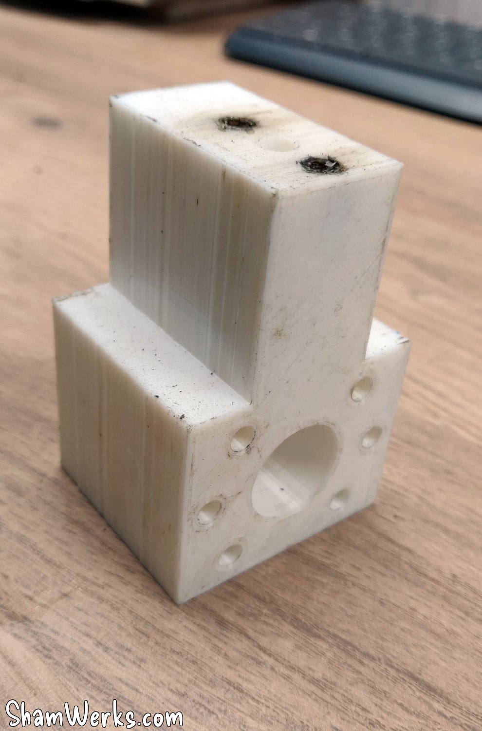
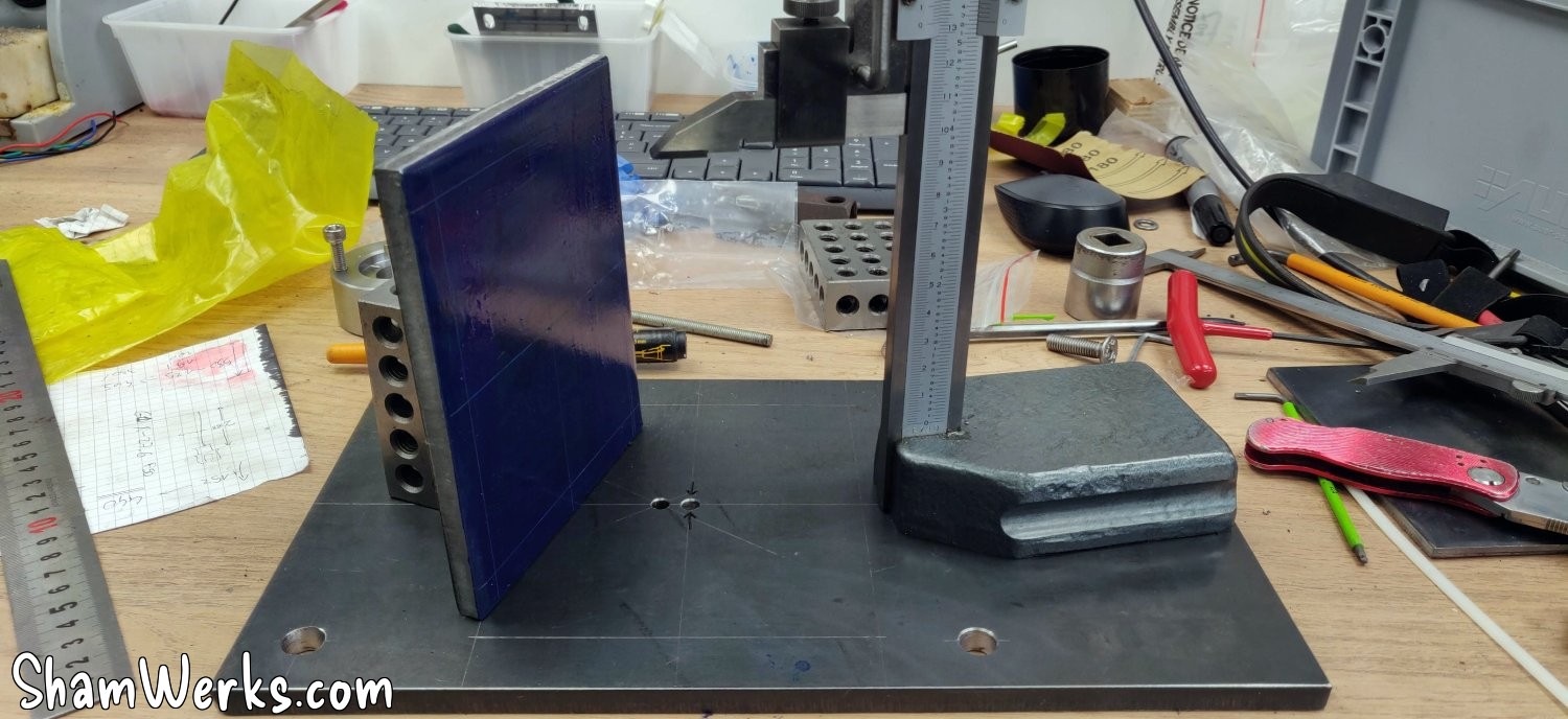
I'm tackling the base of the screw, and the thrust bearing support, which I'm turning in a large steel rod I had in store (I'm really glad I bought a portable band saw just to cut the raw material 😁)... This is where you can't afford to make a mistake (knowing that I'm a beginner in this field, don't underestimate my ability to screw up).
The thrust ball bearing on which the screw rests is a 51104 (20mm x 35mm x 10mm). It looks quite small compared to the original ones, but it's rated for a dynamic load of 14.7kN, or almost 1.5 tonnes, so it should be fine.
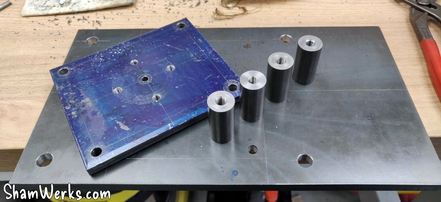
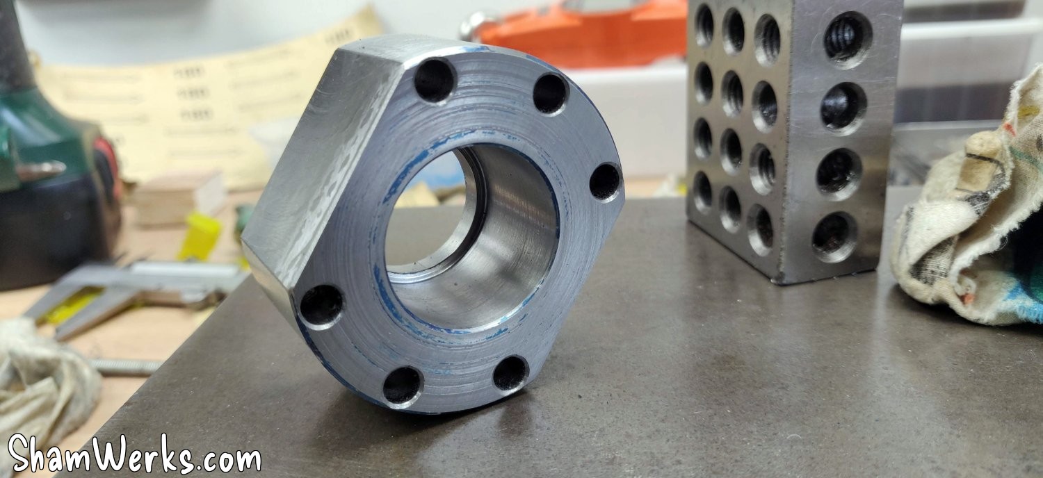
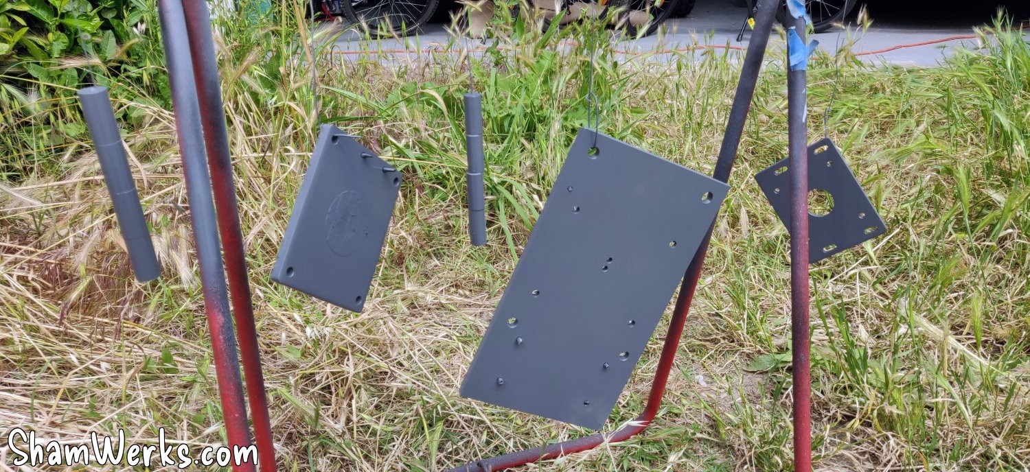
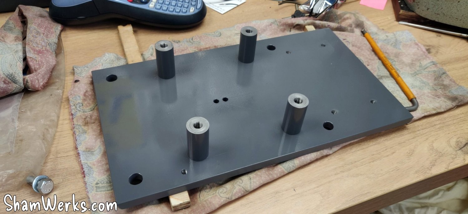
I'm moving on to the structure that will support the screw - the steel plates (from La Mine de Fer and materiel-elevage-online , plasma cutting) of the structure are 10mm thick (except for the one for the motor, 6mm): overkill perhaps, but it has to support the entire weight of the chair and cross table of the machine, and it's quite heavy! The plate stilts are turned from 20mm steel rod (for the ball screw) and 16mm (for the step motor).
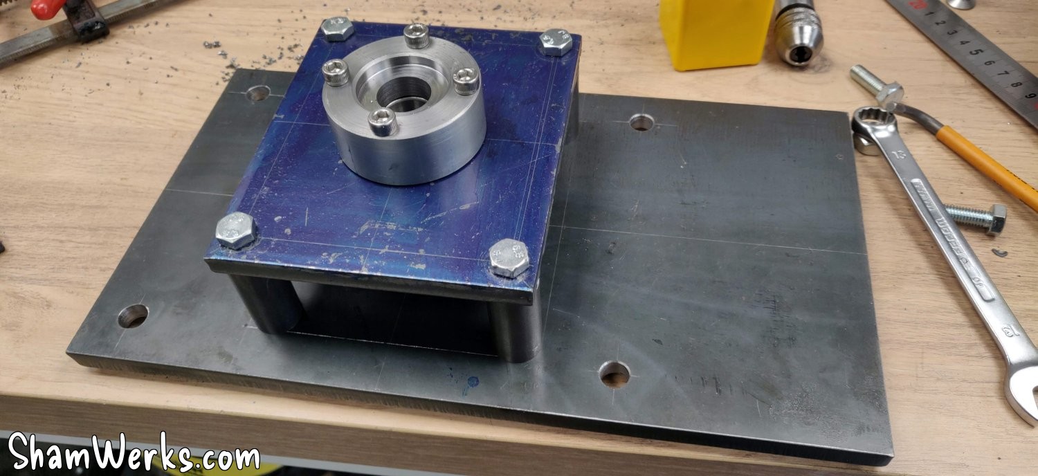
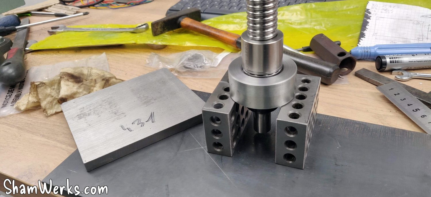
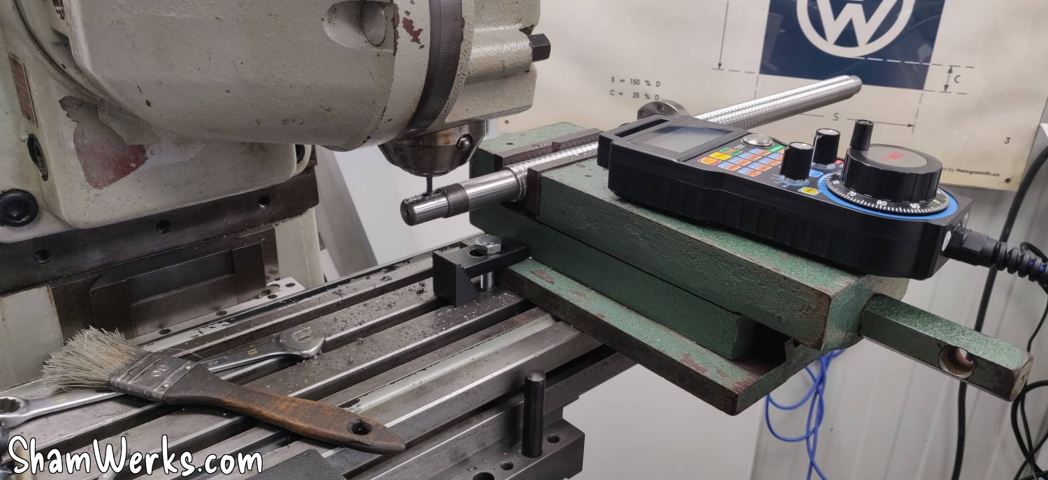
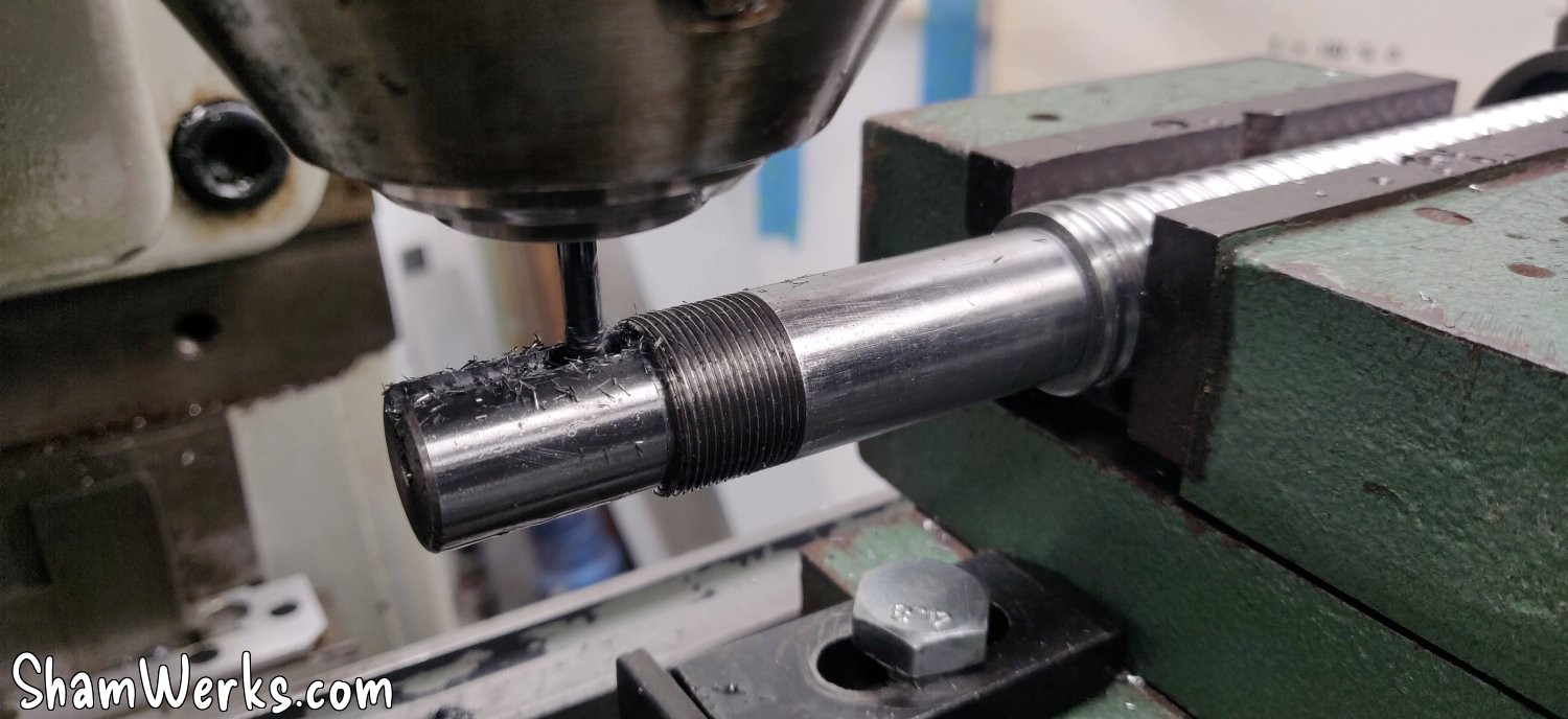
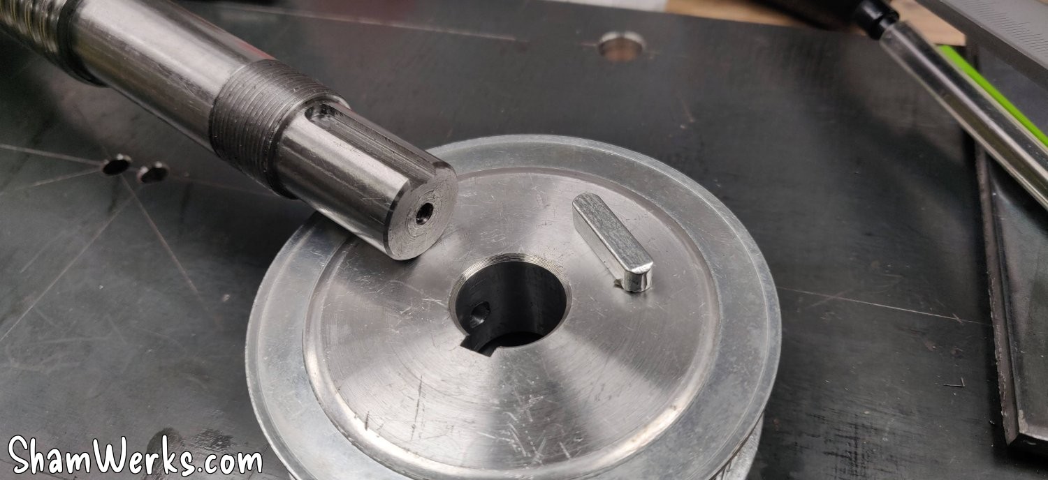
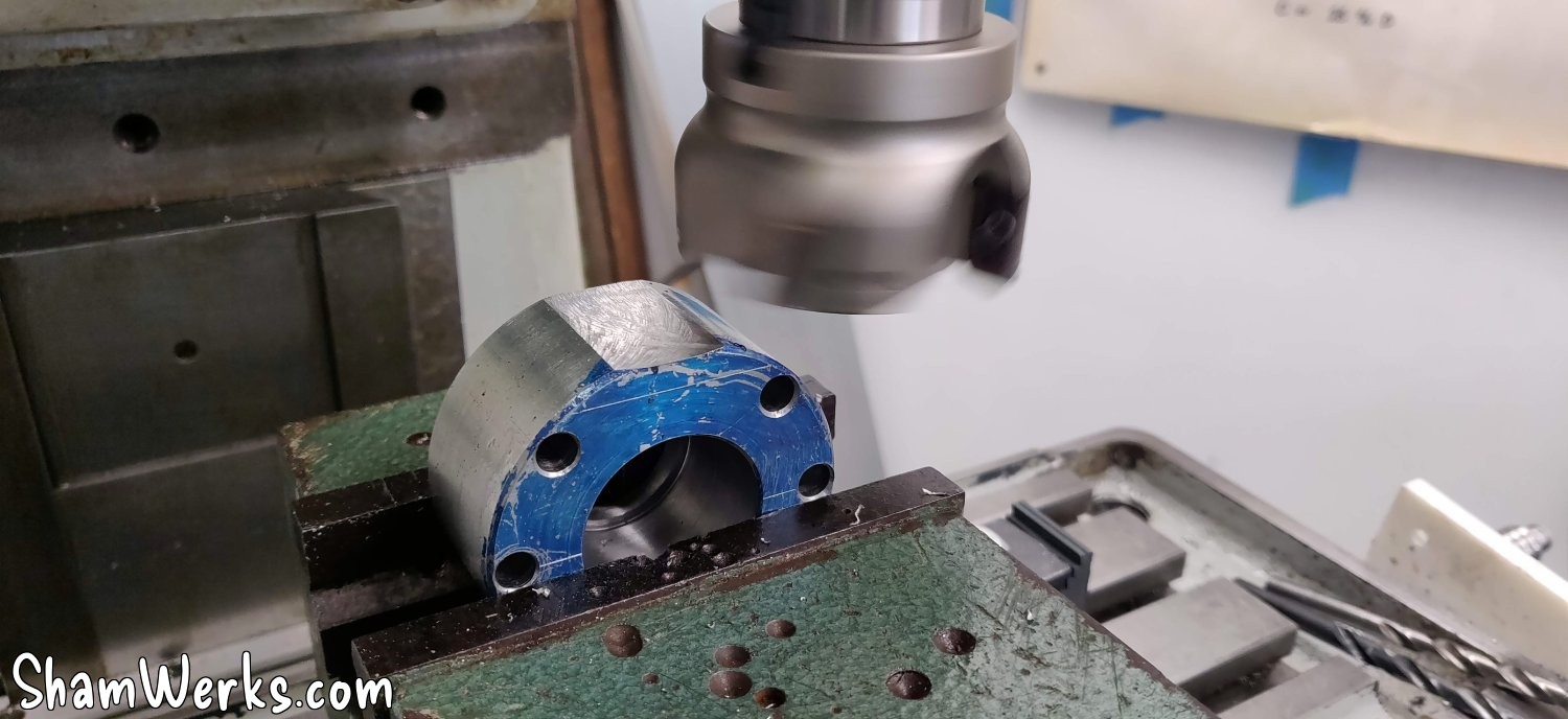
The ball screw didn't have a keyway, and given the torque it will be subjected to, the small pulley clamping screws are obviously insufficient. But since I now have a semi-functional milling machine, I was able to machine the keyway; it was even an opportunity to write my first G-code to automate the cuts 😉 (I was still manually checking the depth of cut, though).
I also had to reverse the ball screw nut, which is always risky (if the balls fall out, it's a nightmare to put everything back in place): thank goodness for the 3D printer again! I made a small tube with an OD of 23 mm and an ID of 20.5 mm, and the operation went smoothly. I must admit I wasn't convinced about the usefulness of a 3D printer in the workshop, but I find new applications for it every day. A definite winner!
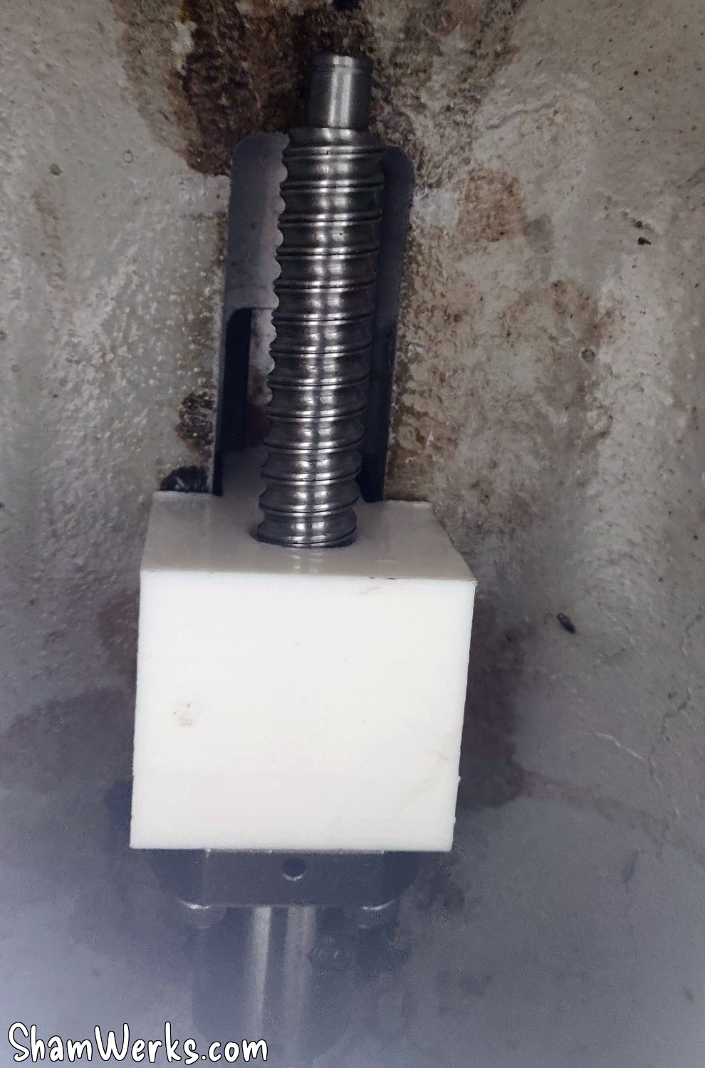
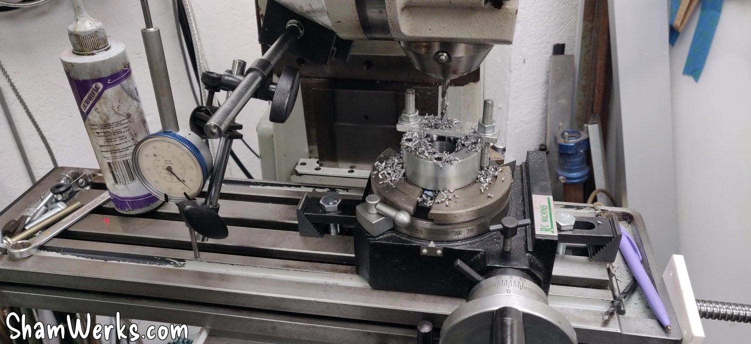
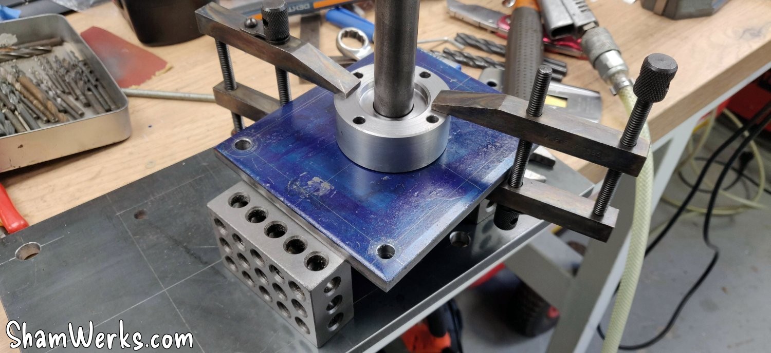
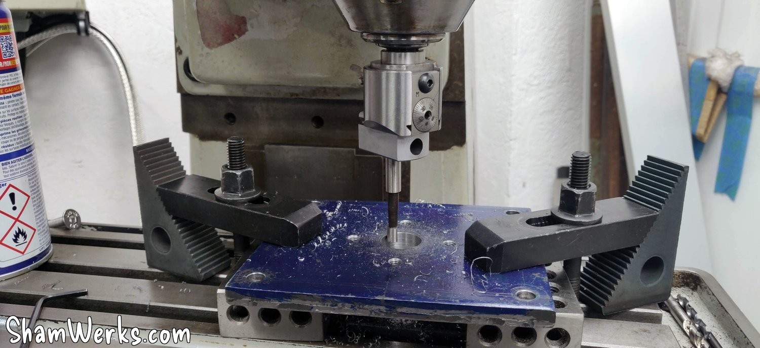
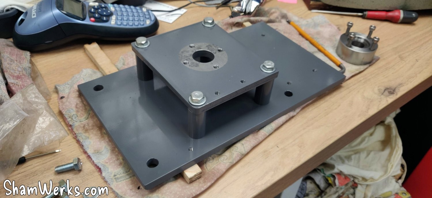
Enlarging the passage for the ball screw to the boring head (I can finally take out all the toys I've accumulated for over 8 years!), and I can do a first dry assembly to see how it fits:
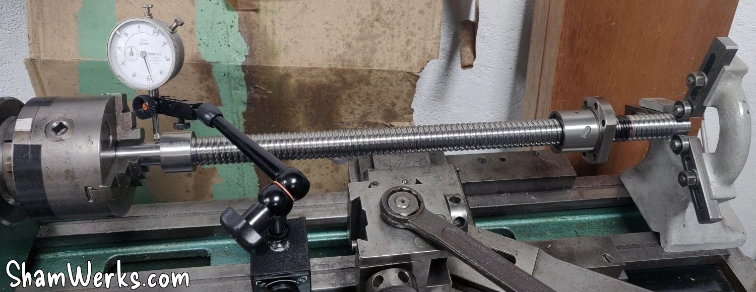
And on the first try, I noticed that the base of the screw I'd turned wasn't perfectly perpendicular, causing a slight runout at the end. So, back to the lathe, with the base properly in place on the screw... And clearly, I'm at the limit of my bed length! 😁😁
It was close, but it did the trick: I whitened the supporting surface, and that eliminated the roundness. Woohoo!
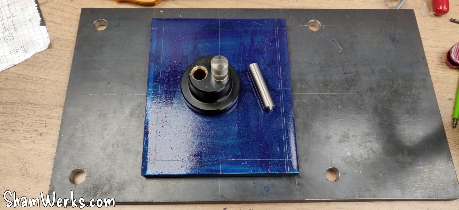
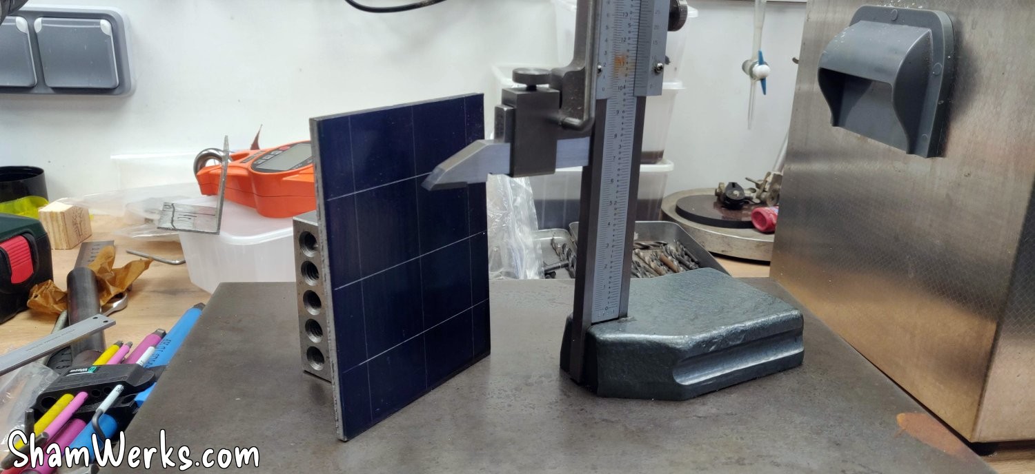
Back to work on the motor mounting plate, cut from a 6mm steel plate (Marking with Precitrace blue, and a marking gauge picked up for €25 on LeBonCoin, a steal!). 😁
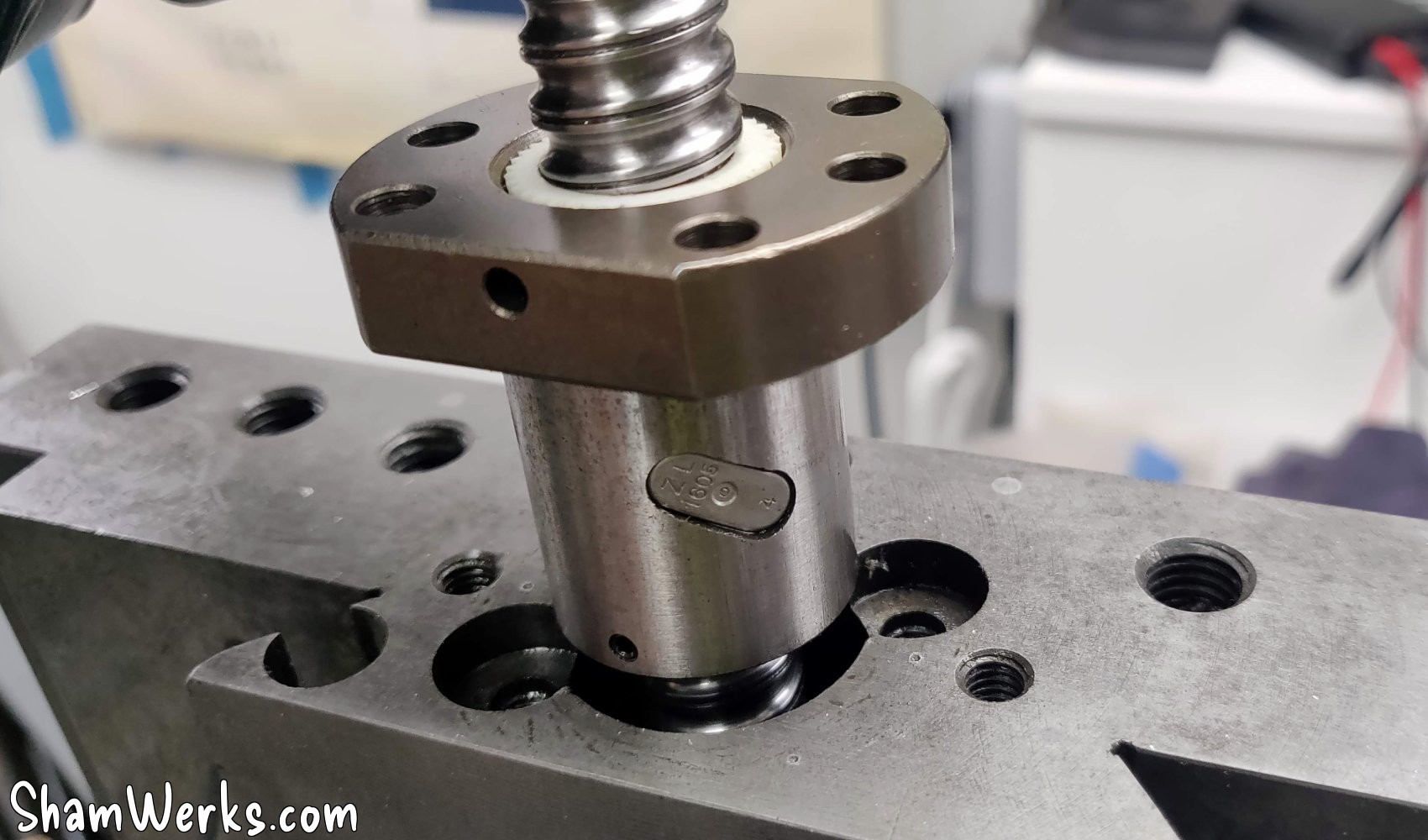
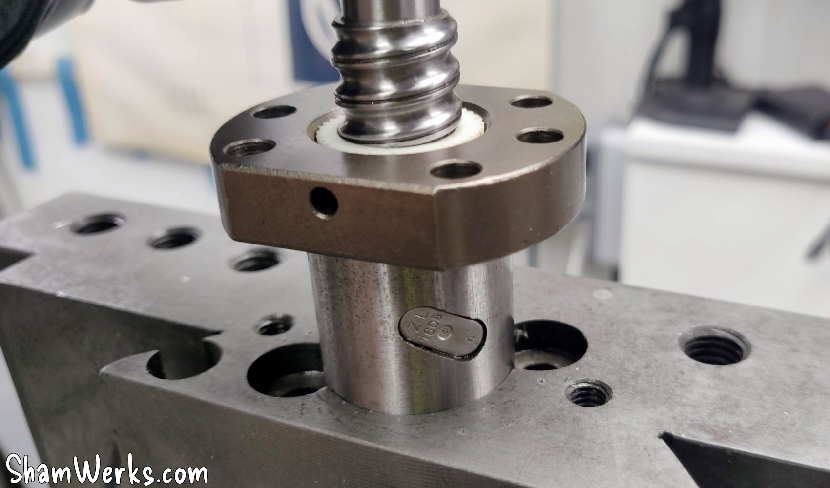
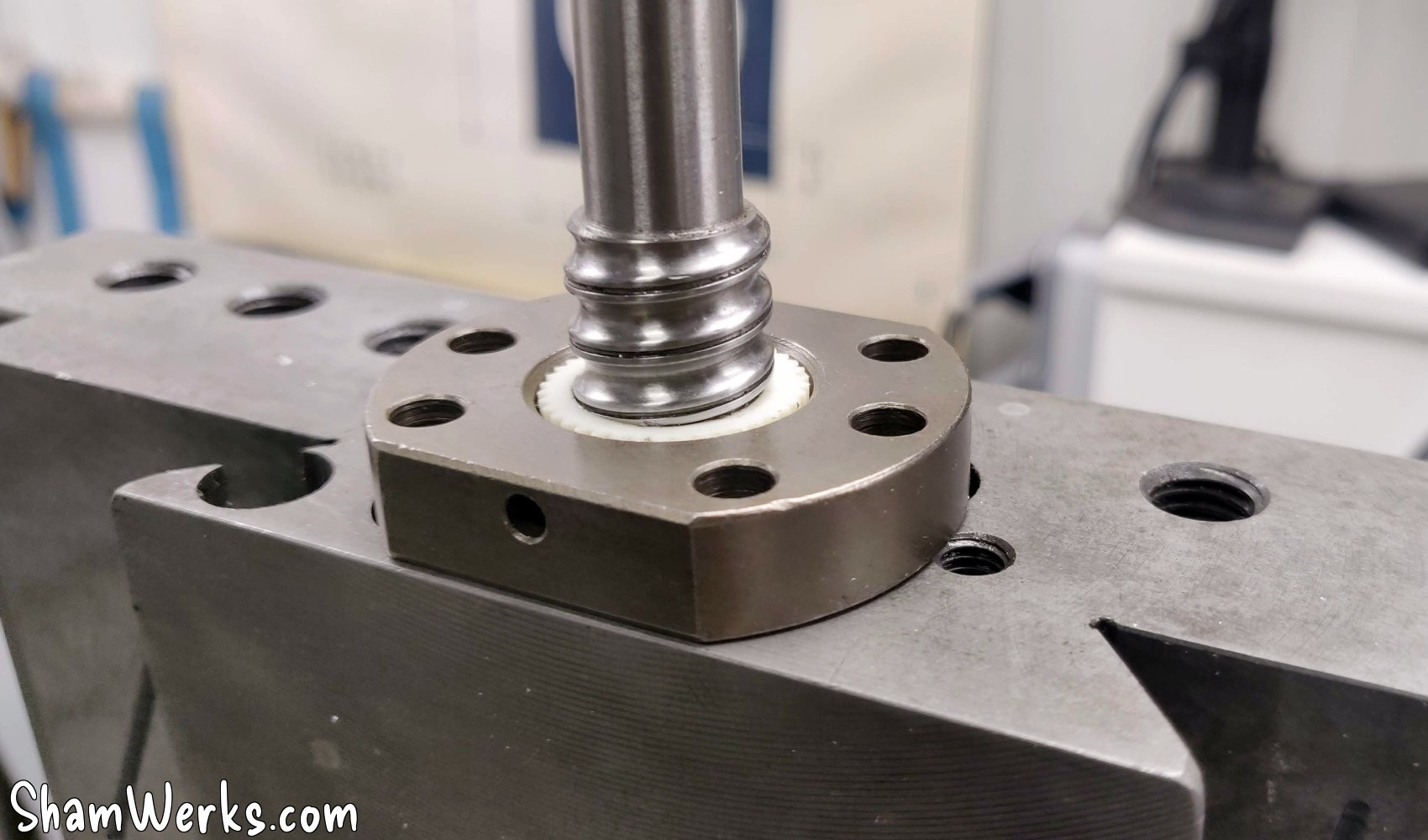
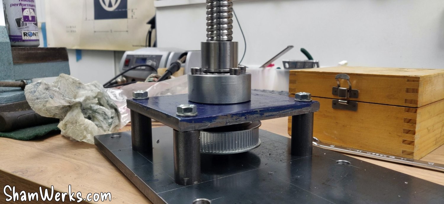
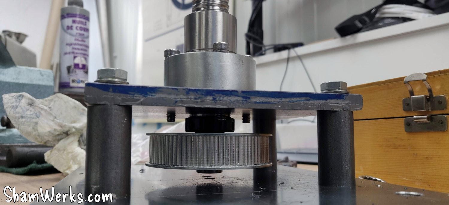
I turn the base of the tube in the same block as before. It is fixed onto the nut of the ball screw via 6 screws, and the tube is then pressed into it using a hydraulic press.
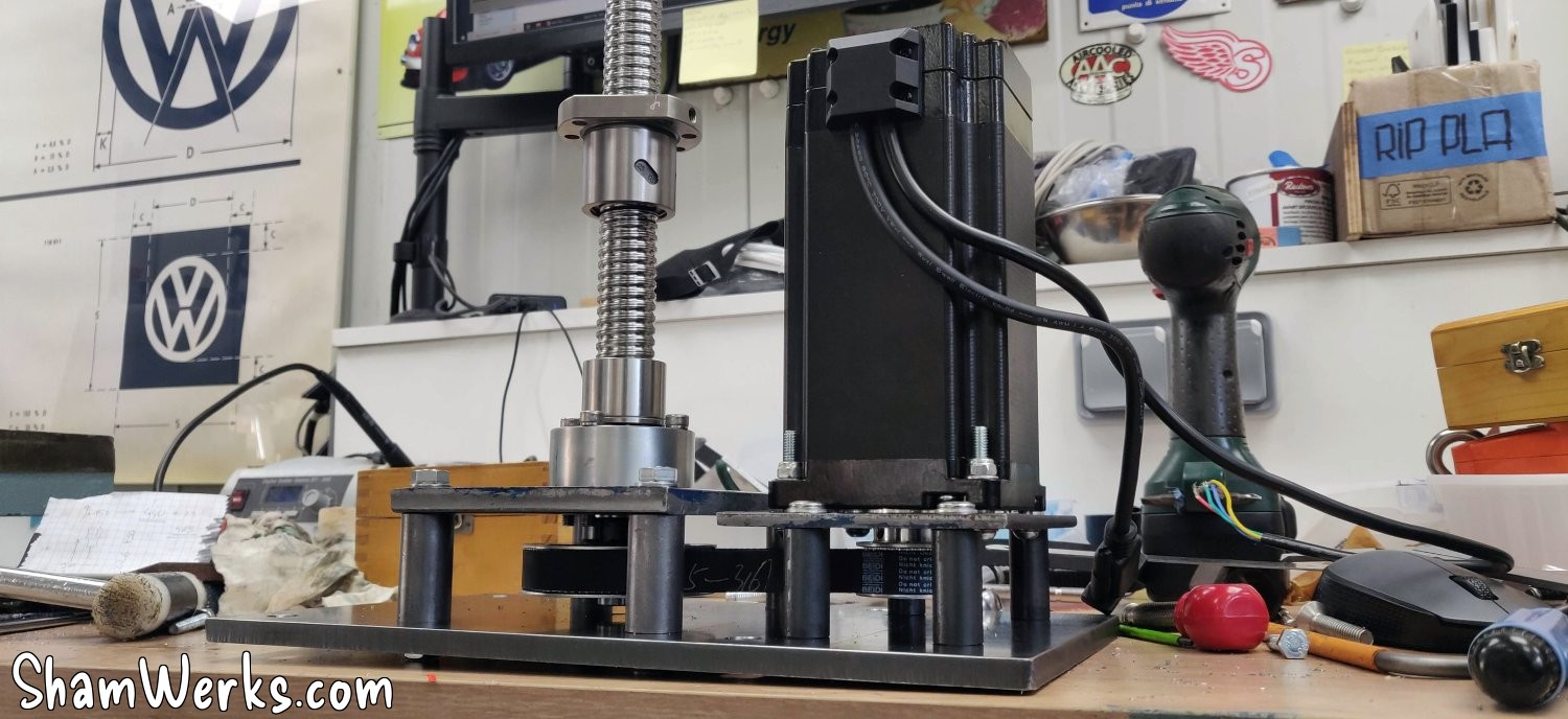
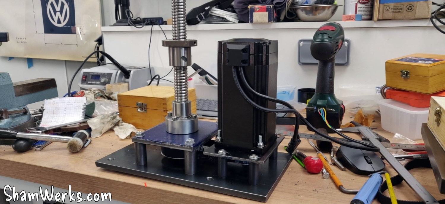
And after all that, my Z axis motor is finally starting to take shape:
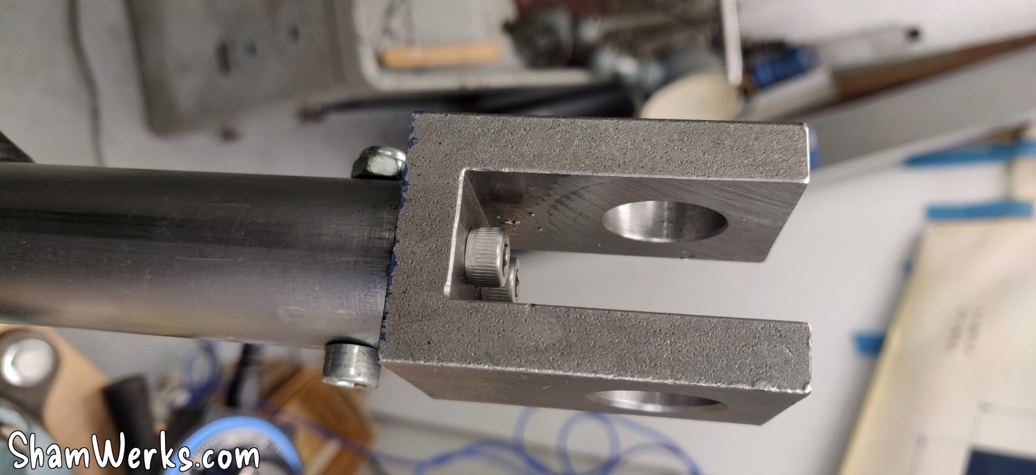
In the end, I couldn't resist modifying the clevis for purely aesthetic reasons: a quick pass with a dividing head to align it with its clamping ring, and it already looks much better... I know myself, if I hadn't done it, that's all I would have noticed on the machine afterwards. #OCD 😉
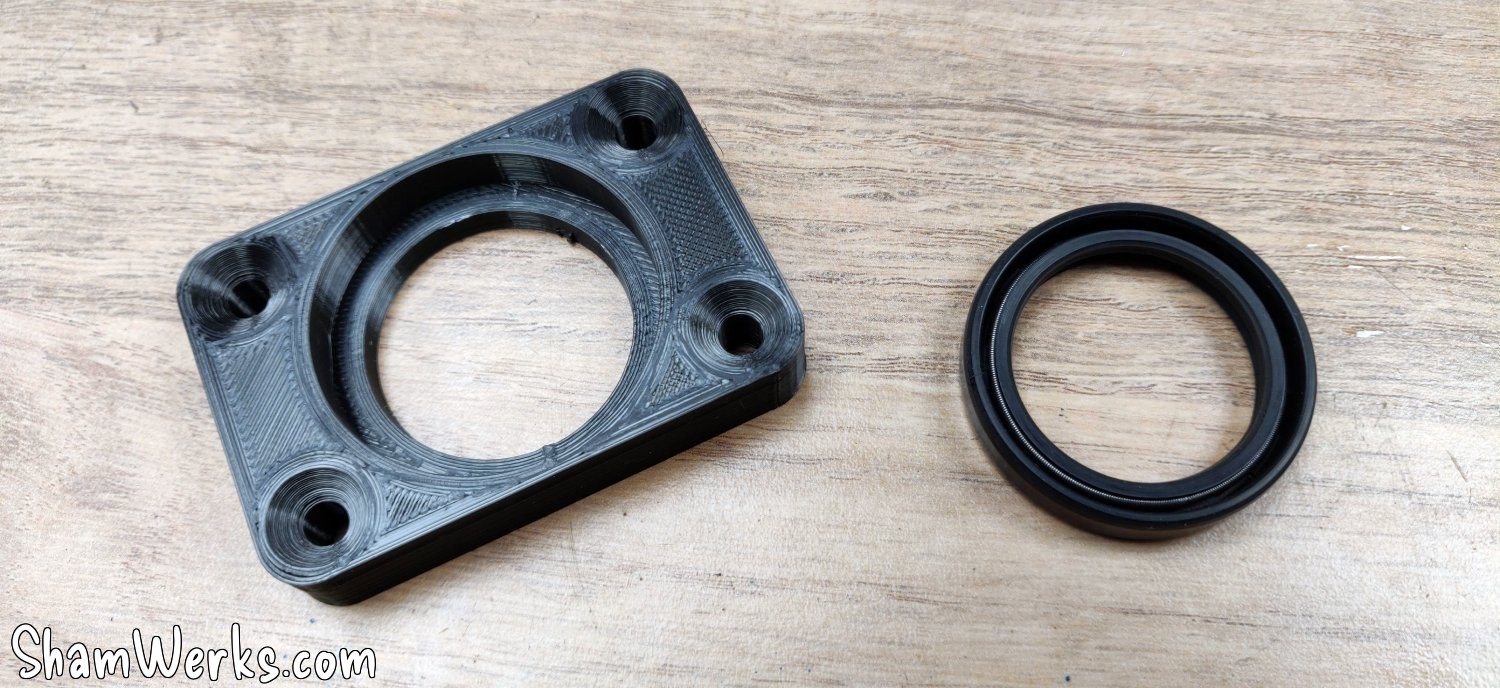
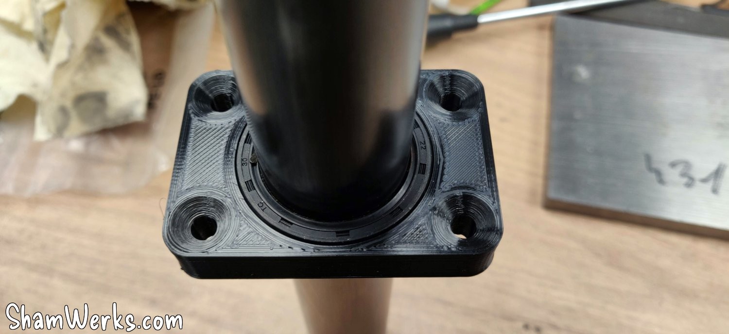
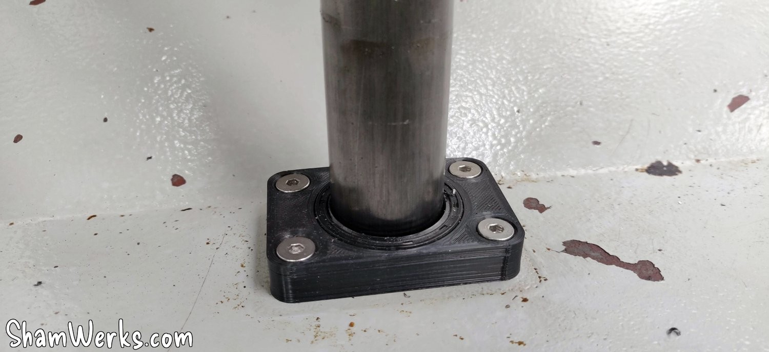
And to prevent the cutting chips/liquid from escaping into the base of the machine, I made a small 3D printed support, with an oil seal, through which the tube slides.
Disassembly, painting, reassembly... And the original mechanism is definitely removed.
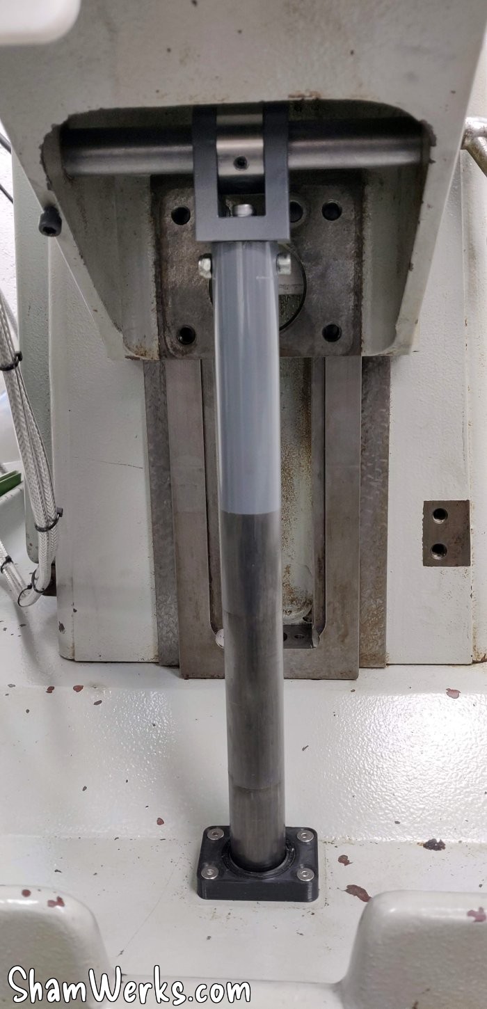
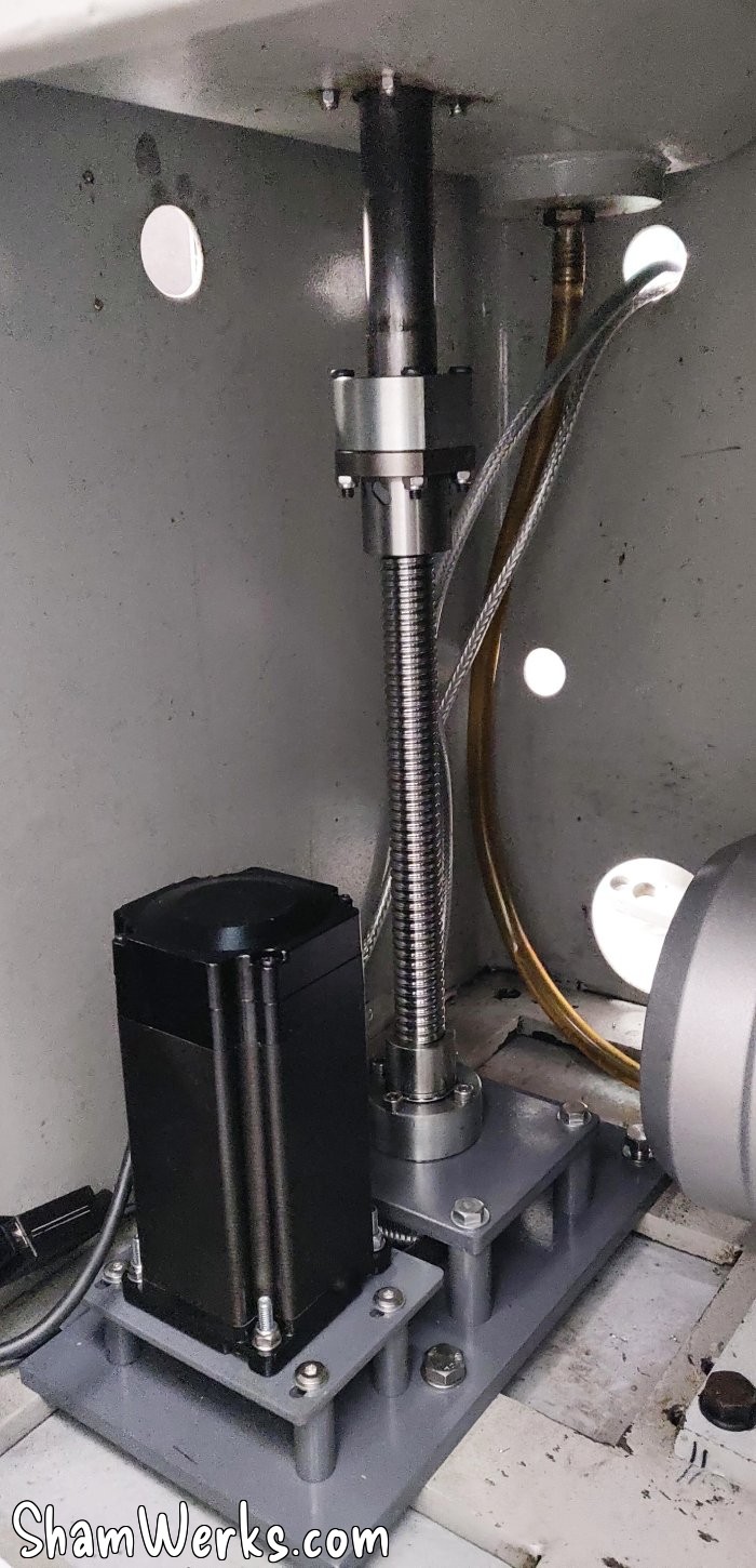
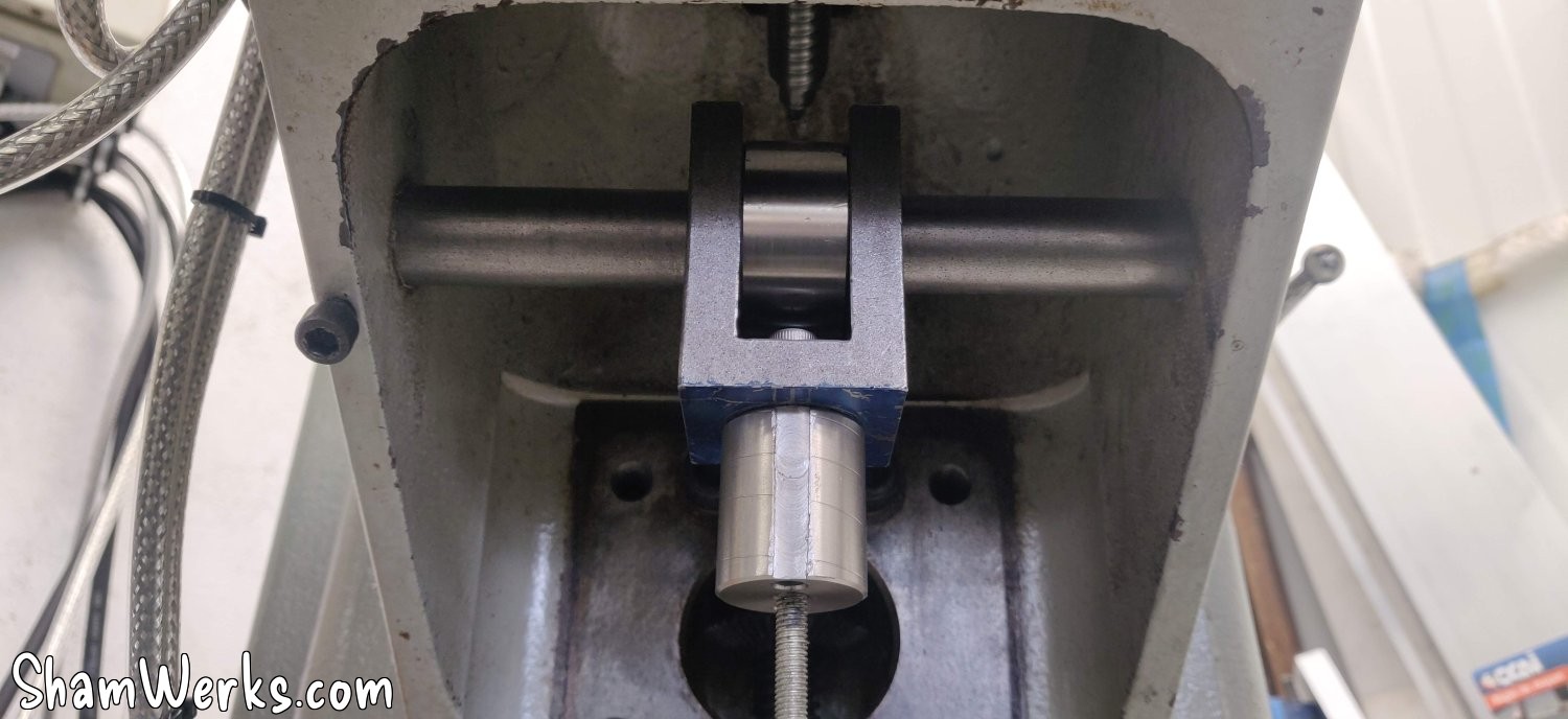
And FINALLY, I can stick everything into the milling machine.
I was expecting to just do a first dry run, have to calibrate, adjust...
And then no.
Everything worked perfectly the first time, everything aligned perfectly.
And I'm the first to be surprised. 😁😁
I was also worried the motor would struggle to go up; in the end, it didn't show the slightest sign of difficulty, nothing, zero... Even when I grabbed the screw with my whole hand and tried to slow it down. Sometimes oversizing has its advantages. 😉
On the cons side, it's a bit tricky to put this motor in the machin or take it out of it. I have to assemble everything piece by piece directly in the base, it's impossible to put the whole thing in at once, there's not enough room to maneuver.
In fact, I'm 15mm short of the machine's full upper travel; I might add a shim under the bracket. Simply making the tube longer is impossible; it already fits perfectly in the machine base, and making it longer would make it totally impossible to squeeze it in.
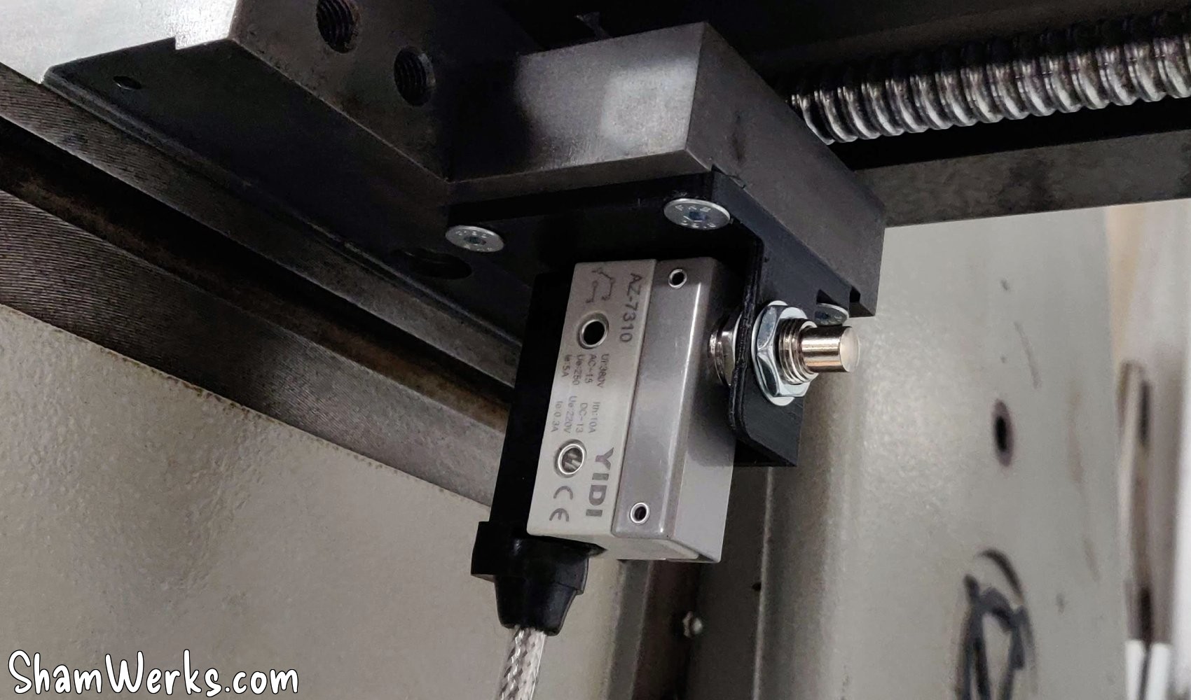
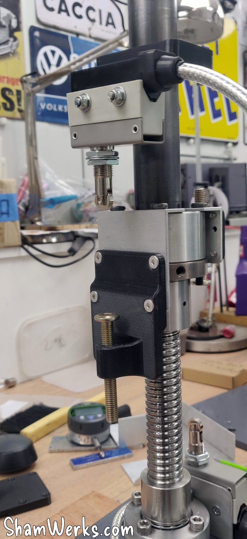
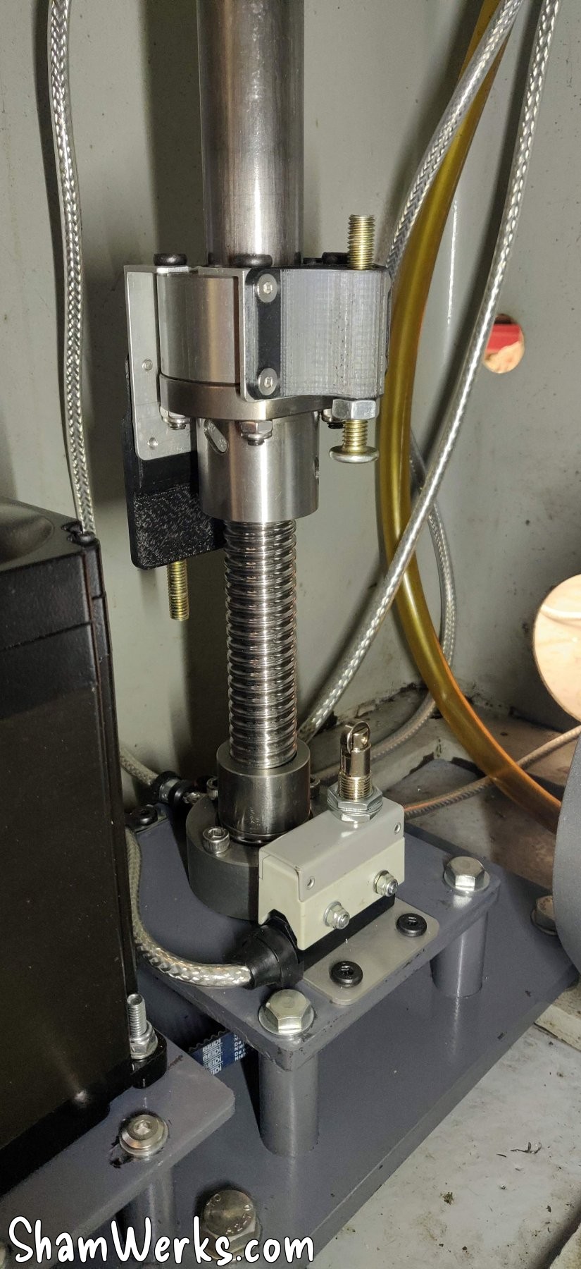
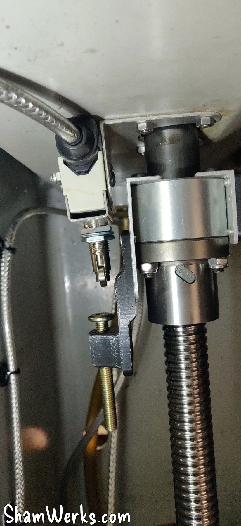
I'm finishing up with the Z-axis limit switches to avoid breaking anything when reaching the limits of movement. During my tests, before installing the limit switches, I reached the upper limit and kept going up... The motor immediately started bending the base plate! 😮
A little bit of thought, some aluminum angle brackets and a little 3D printing and I have functional limit switches.
After calibrating the steps in millimeters in Mach3, and setting the backlash to 0.8 mm (inevitable with a belt drive, there's always a side of the belt under tension, and a bit of sloppiness in the other), I have a repeatability on the order of one hundredth of a mm. I can't ask for more, I'm a happy camper!
Initial tests and conclusion
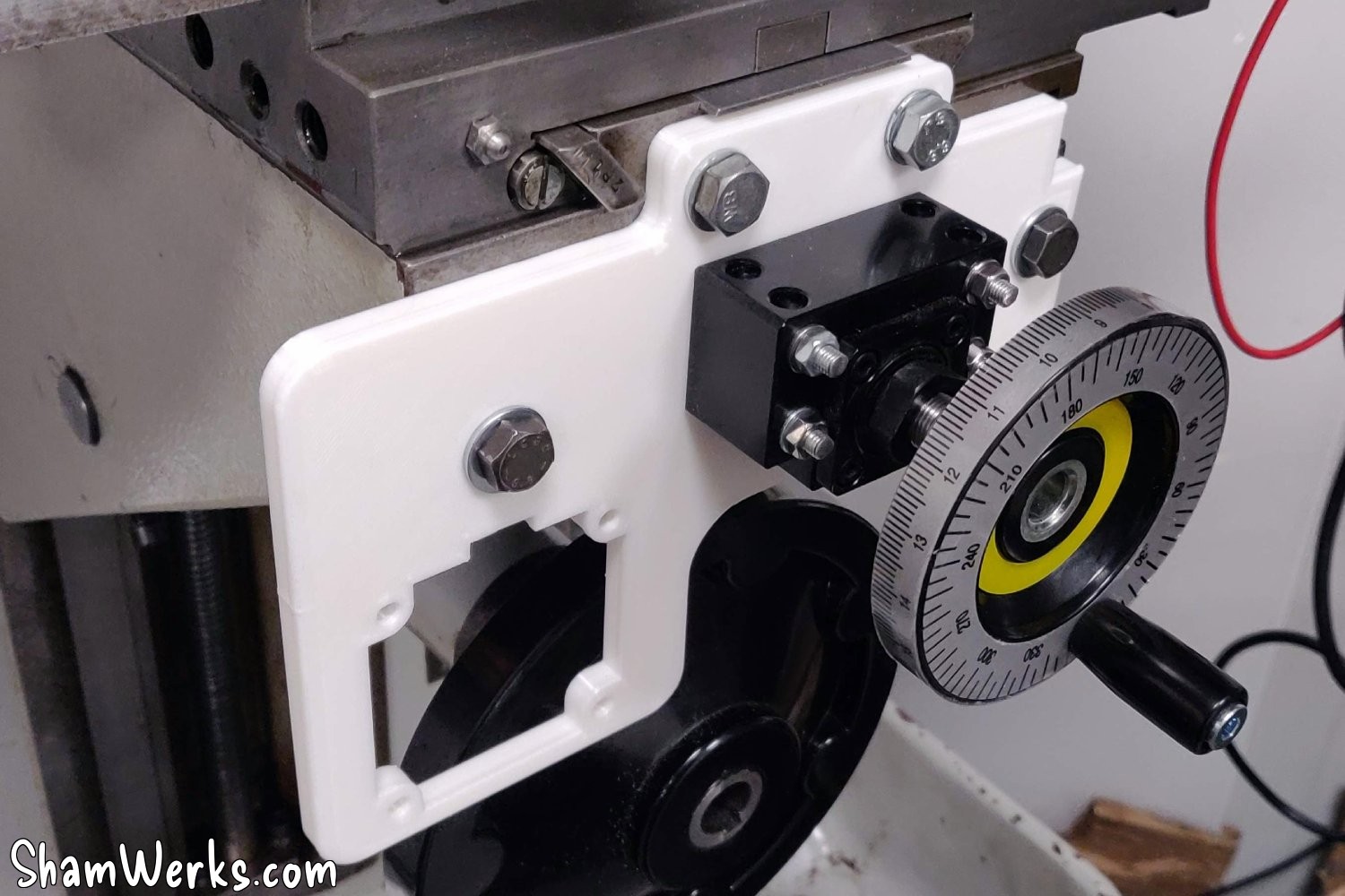
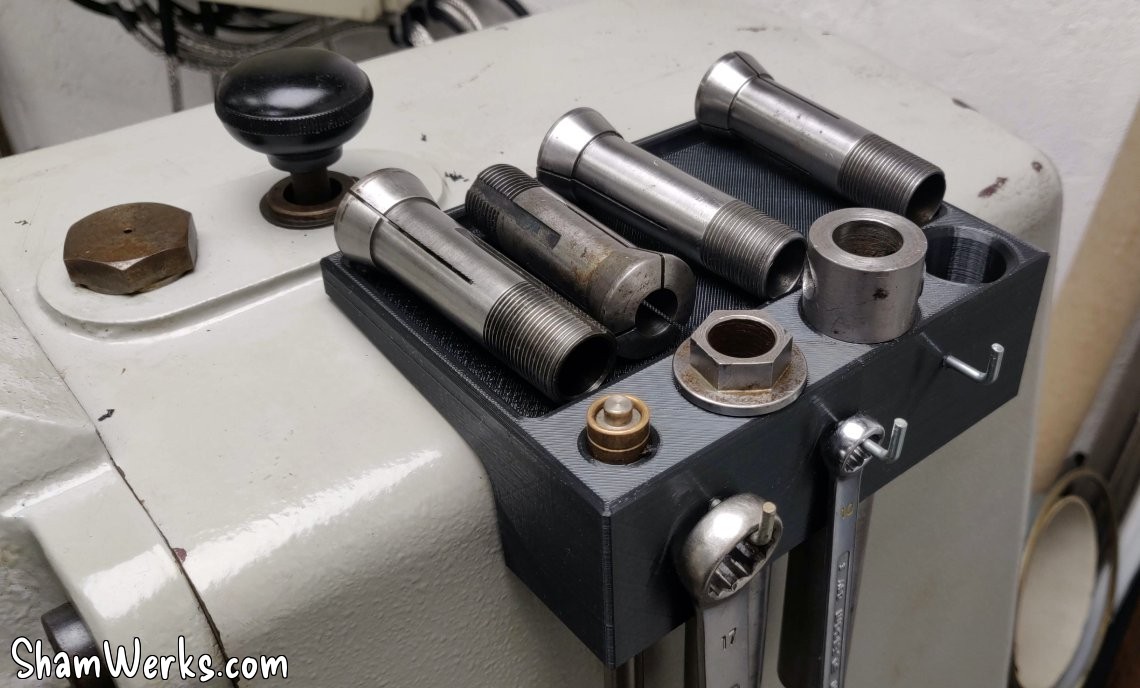
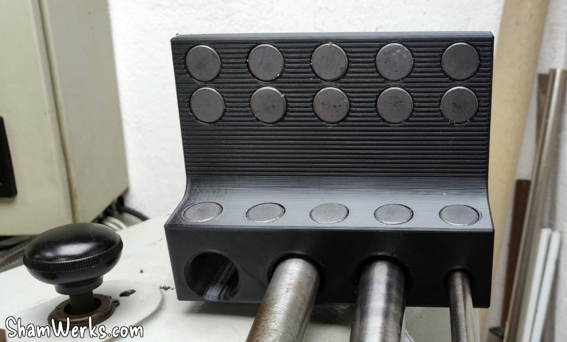
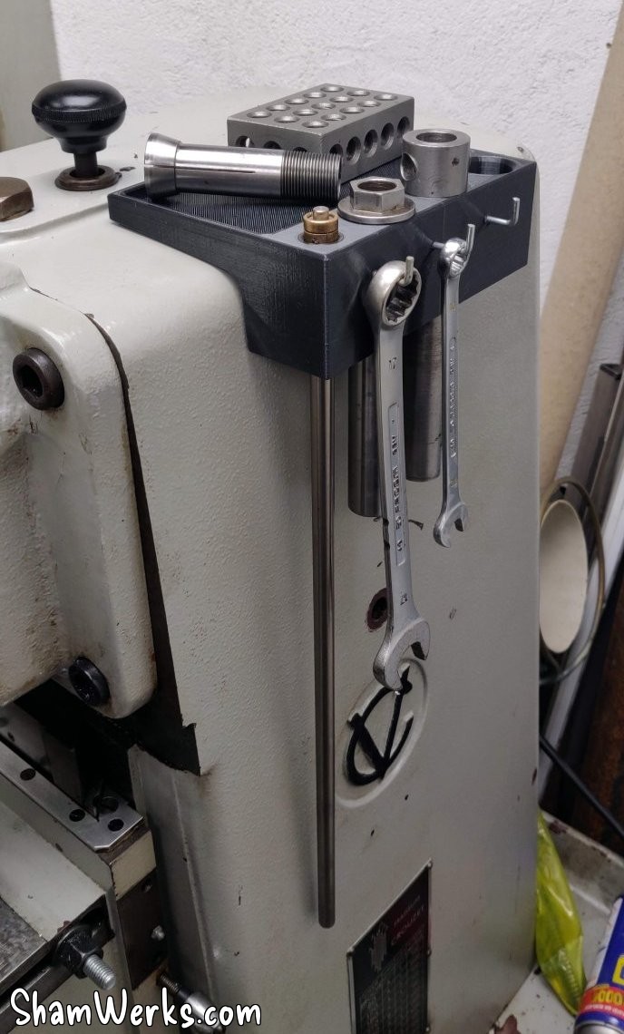
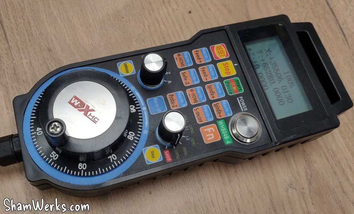
I added a USB controller (MPG, or Manual Pulse Generator) found on AliExpress – connected to the PC via USB. They also exist with Bluetooth, but I didn't want to introduce a potential weak point in the system. I also made a small 3D-printed magnetic tool holder, which I attached to the side of the machine, and there you have it, a working milling machine!
Short video demonstrating the system in action:
As it stands, the milling machine is running, and all three axes are motorized and usable. The precision on X and Y is limited due to the PLA plates (flexing under stress, loosening the belt, which can cause it to skip a tooth), but it should be sufficient for machining the final adapters. It also allows me to roughly configure Mach3 to control everything.
Stay tuned for the next episode, which will cover the finalization of the motor mounts, lighting, control box, stops... among other improvements. 😉
Honestly, buddy, if you've read this far, you probably don't have much popcorn left. Consider that I owe you a cookie; you can ask me for one in the comments! 😉😁🍪
Published on 01/02/2026 / 4 commentaires